3025SW Master Control Switching & Channel Branding
Page 10 Revision 1.0
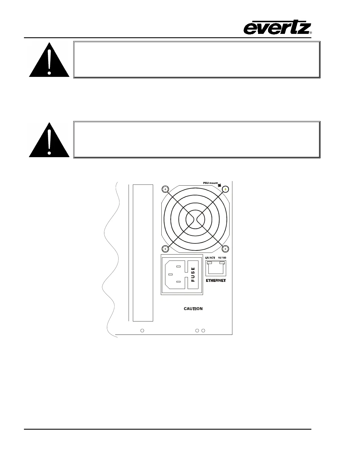
CAUTION: To reduce the risk of electric shock, you must replace the mounting
screw after replacing the power supply.
2.6. POWER
The power entry modules contain a standard IEC power inlet connector, two 5 x 20 mm fuse holders,
and an EMI line filter.
CAUTION: The EMC frame is shipped with 10 Amp fuses rated for 100-120 VAC
operation. If you are operating the EMC System in a country with nominal 220-
240 VAC operation, replace the fuses with 6.3 Amp fuses rated for 220-
operation. See section 2.5.1 for information on changing fuses.
2.6.1. Connecting the Power
THIS EQUIPMENT HAS MORE THAN ONE POWER
SUPPLY CORD. TO REDUCE RISK OF ELECTRIC SHOCK
GROUNDING OF THE CENTER PIN OF POWER SUPPLY
CORD PLUGS MUST BE MAINTAINED. DISCONNECT
BOTH POWER SUPPLY CORDS BEFORE SERVICING
FUSE: 100-120V: T10AH250V
220-240V: T6.3AH250V
Figure 2-2: Connecting the Power to the Frame
The EMC frame comes standard with one auto-ranging power supply that automatically senses the
input voltage over the range of 100 to 240 VAC. An additional power supply can be ordered to provide
fully redundant powering of the frame. When only one power supply is fitted, the frame will be fitted
with a fan module to ensure the thermal integrity of the frame cooling. In a frame that contains a
redundant power supply module, each power supply may be powered from a different AC mains
source, allowing complete AC supply redundancy.