4. Commissioning positioning systems
4−29
Festo P.BE−SPC200−WIN−PISA−CD−EN en 0901d
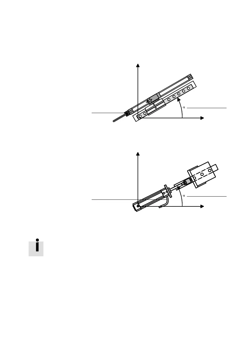
1 Measuring system
connection
2 Fitting position
+90°
0°
1
2
Fig.4/10: Fitting position of rodless drives (example DNCI−...)
1 Measuring system
connection
2 Mounting position
+90°
0°
1
2
Fig.4/11: Fitting position of piston−rod drives (example DNCI−...)
If the supply pressure is modified by more than 1bar and if
the mounting position is modified, the identification data will
be reset (see section 4.6).
With the following four parameters you can specify the refer
ence points of your positioning system.
Note that the software end
positions and the project zero
point refer to the cylinder zero point. If you modify the mount
ing offset or the reference position, the SPC200 will check to
see if the resulting new reference points still lie within the
range of the measuring system. If this is not the case, an ap
propriate
fault message will be displayed.
 Loading...