5. Programming
5−31
Festo P.BE−SPC200−WIN−PISA−CD−EN en 0901d
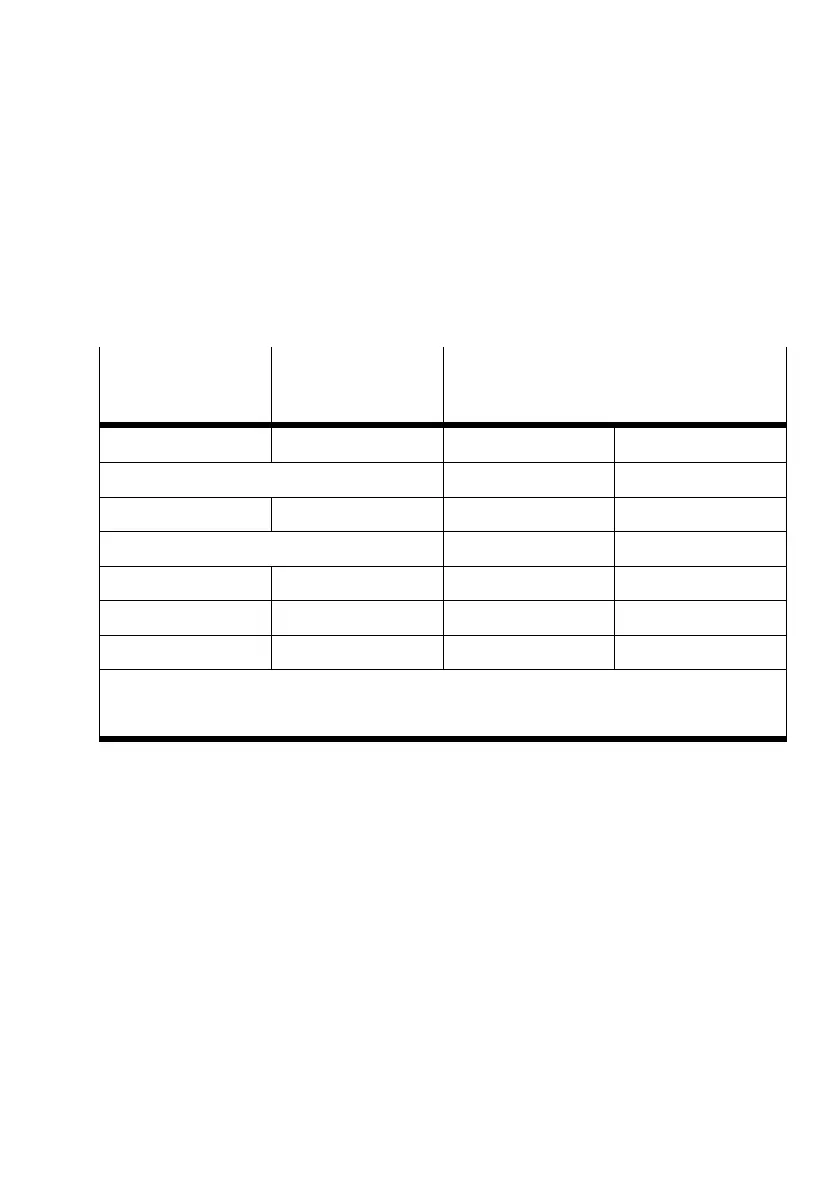
I/O address range The assignment of the I/O address range depends on the
configuration of the SPC200. If a field bus module is fitted,
the address range will remain 0.0 ... 0.9 unassigned. The
assignment of the I/O addresses for configuration with and
without field bus module is shown in the following table:
Configuration
without
field bus
module
Configuration with
field bus module
Max. address range
First I/O module
1)
I0.0 ... I0.9
1)
2)
Q0.0 ... Q0.7
1)
2)
I/O module on the first axis interface string I1.0 ... I1.15 Q1.0 ... Q1.15
Second I/O module First I/O module I2.0 ... I2.9 Q2.0 ... Q2.7
I/O module on the second axis interface string I3.0 ... I3.15 Q3.0 ... Q3.15
Third I/O module Second I/O module I4.0 ... I4.9 Q4.0 ... Q4.7
Fouth I/O module Third I/O module I5.0 ... I5.9 Q5.0 ... Q5.7
3)
Field bus module I10.0 ... I13.15
2)
3)
Q10.0 ... Q13.15
2)
3)
1)
Address range is not available if a field bus module is used
2)
Control inputs and outputs are reserved by pre−assigned functions
3)
Address range is not available without a field bus module





 To Next Page