3-10 Section 3: Model 9500B Controls: Modes of Operation Descriptions assume 9500B/1100
3. Use Direct edit to set the required reference
frequency. After typing the value press the
↵ key on the keypad (the Direct edit 'V'
screen key in the right-hand column will
perform the same action).
4. The '50kHz DEFAULT' screen key on the
right can be used if 50kHz is required.
5. Press the EXIT screen key to return to the
'Present settings' menu screen. The new
reference frequency appears on the 'Present
Settings' list.
3. Use Direct edit to set the required high
voltage warning limit. After typing the
value press the ↵ key on the keypad (the
Direct edit 'V' screen key in the right-hand
column will perform the same action).
4. The 'DEFAULT 100V' screen key on the
right can be used if 100V is the required
level.
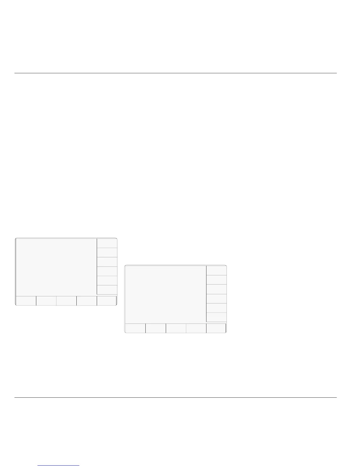
TODAY'S DATE TIME
Configuration
The high voltage warning limit
can be changed by using direct
editing only.
The maximum value is 11ØV
Limit =
EXIT
DEFAULT
100 V
1ØØ.ØØ V
5. Press the EXIT screen key to return to the
'Present settings' menu screen. The new
high voltage threshold value appears on
the 'Present Settings' list.
Note: Out-of-Range Indication
The valid range of limit values is from 10V to
110V. When values outside this range are
entered, an error message will appear on the
screen, and the 'EXIT' screen key label will be
replaced by 'OK'. By pressing 'OK' the original
value is reinstated and the message disappears,
for a second attempt.
3.4.3.4 'Bus address'
Remote Operation via the IEEE-488
interface — Addressing the 9500B
When the 9500B is set for remote operation,
control is removed from the front panel and
given to an external controller.
Communication is set up between the 9500B
and its controller via the IEEE-488 bus,
connected into an interface within the 9500B.
Commands from the controller are addressed
to the 9500B using an address code, which can
be a number in the range 0-30. For the 9500B
to respond, this number must be matched by
the same number programmed into the 9500B
using the procedure given below.
Remote operation of the 9500B via the IEEE-
488 interface is described in Section 6.
N.B. The correct bus address is necessary to
use remote commands, but remote
operation is available only when the
instrument is in MANUAL or
CALIBRATION mode.
1. The 9500B IEEE-488 bus address can be
set to any number within the range 0 to 30.
For access from the 'Present Settings'
screen, press the BUS ADDRESS screen
key at the top right.
2. The 9500B transfers to the 'IEEE 488
ADDRESSES' screen:
TODAY'S DATE TIME
Configuration
The
REFERENCE FREQUENCY
can be changed by using
direct editing only
.
Ref =
EXIT
5ØkHz
DEFAULT
5Ø.ØØ kHz
3.4.3.3 'Safety voltage'
High Voltage Warnings — Warning and
Interlock
In the interests of safety, to avoid electric
shock, the 9500B incorporates a high-voltage
warning and interlock system for both DC and
Square Voltage functions. The limit can be set
to any voltage from 10V to 110V. The default
warning threshold value (100V) can be changed
in Configuration mode. The active threshold
value is stored in non-volatile memory.
When the output is on in DC/Square or High
Edge function, the warning will sound when
the output voltage setting is raised to or above
the threshold value. The output will stay at its
previous value until the user confirms the new
voltage by re-pressing the OUTPUT ON button.
1. For access to allow the high voltage
warning threshold to be altered, press the
VOLTAGE LIMIT screen key on the
'Present Settings' screen.
2. This transfers to a configuration screen
designed for changing the 'Voltage Limit'.
The default value is shown:
3.4.3.2 'Ref Frequency'
Use of Reference Frequency
The reference frequency is used mainly in
assessments of UUT oscilloscope bandwidth,
a commonly used frequency for this purpose
being 50kHz. In the 9500B, for ease of
operation in certain functions, the output can
be changed from the selected frequency to the
reference frequency and back by a simple
toggle switching action.
In the 9500B, the default reference frequency
is set at 50kHz, but users can change this in
Configuration mode to match the frequency
used in procedures for individual oscilloscopes.
1. For access to alter the reference frequency,
press the REF FREQ screen key at the
bottom left of the 'Present Settings' screen.
2. This transfers to a configuration screen
designed for changing the 'Ref Frequency'.
The default value is shown: