Infratec™ 1241 Grain Analyzer
5:6 Service Manual 1001 5015 / Rev. 4
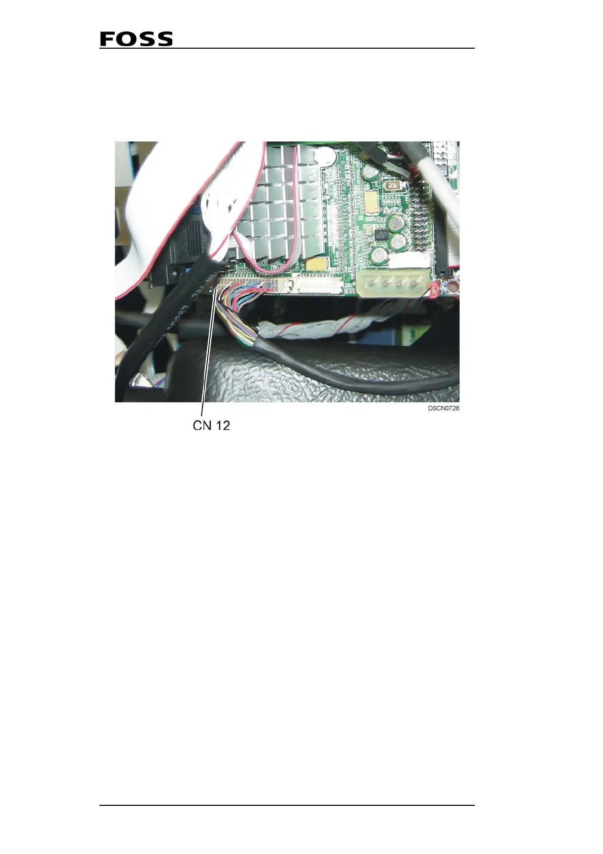
11. Remove the display cable from CN12 on the Processor Board.
NOTE! Observe the display cable orientation.
Fig. 5:7 Processor Board
12. Fit the new display cable to CN12 on the Processor Board.
NOTE! The display cable should be placed as before on the upper
side of the PC Module.
13. Tilt up the PC Module and fit the two locking nuts holding the PC Module.
14. Fit the new LCD Display with the four distance bolts together with the two tooth
lock washers. Place the tooth lock washers where the Inverter Interface Board
should be mounted.
15. Fit the new Inverter Interface Board with the two distance bolts together with the
two nylon washers.
16. Connect the JP1 and JP2 cables to the Inverter Interface Board.
NOTE! Use extreme care when connecting these cables.
17. Connect the display cable to CN1 on the LCD Display.
18. Connect the P1 cable to the DSP Board.
19. Close the left-hand door and fit the new covers. Switch on the instrument.
CN12 LCD Display
 Loading...