Figure 12
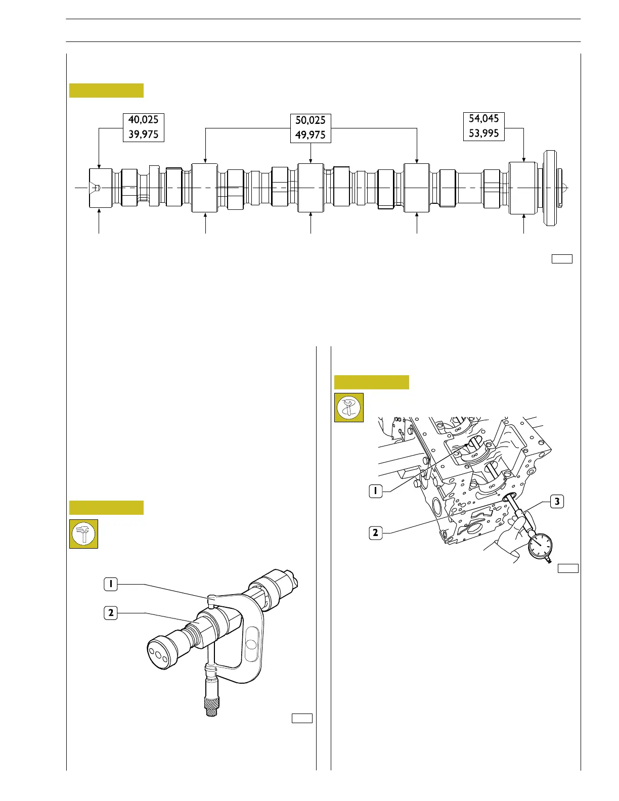
TIMING SYSTEM
Camshaft
119551
MAIN DATA ABOUT CAMSHAFT PINS
Thesurfaceofthecamshaftpinsandofcamsmustbe
extremely smooth. In case any trace of meshing or scratches
are detected, replace the shaft and the relevant bushes.
70171
Figure 13
Using a micrometer (1), check the diameter of the camshaft
(2) supporting pins on th e two perpendicular axles.
Checking cam lift and pin alignment
Place the camshaft on footstocks and, throughout a
centesimal comparator placed on the central support, check
that the radial oscillation does not exceed 0.015 mm
otherwise replace the shaft.
70172
Figure 14
The front camshaft bush (2) must be thrust in the respective
seat.
There must be no trace of meshing or wear in the inner
surface.
Using a bore meter (3) measure the front adiameter of the
camshaft bush (2).
Measurements must be made on two perpendicular axles.
BUSH
SECTION 4 - MECHANICAL OVERHAUL
13
F32 SERIES
Pri nt P2D32F005 E Base - April 2009