Rocker cover blow-by removal and refitting
Figure 65
133191
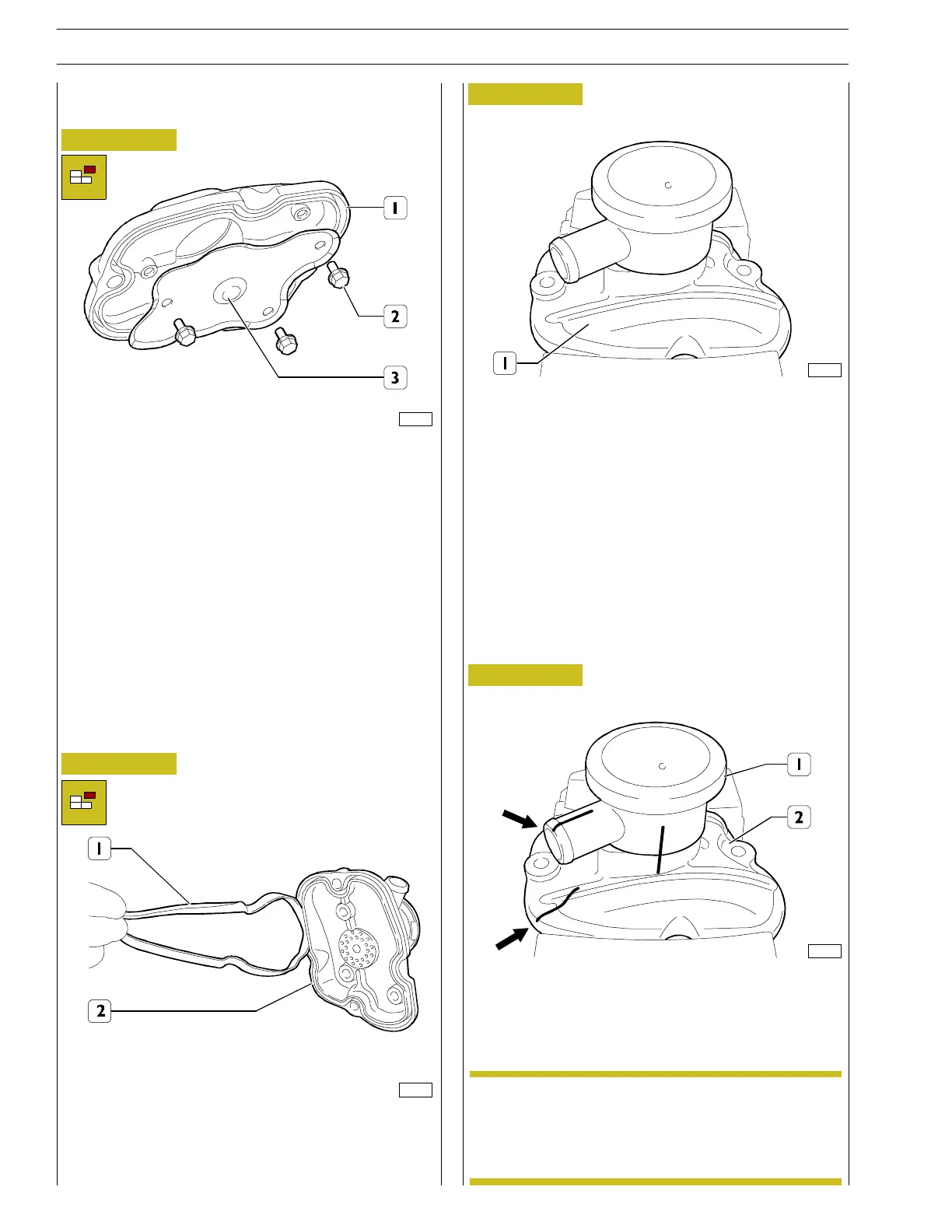
- Unscrew the screws (2) from th e tappets co ver (1) wi th
theblow-byfilterandremovetheplateguard(3).
Figure 66
133192
- Remove the gasket (1) from the roc ker cover (2).
Figure 67
133193
- Secure the rocker cover (1) in a vice.
Figure 68
133199
- Mark th e relative position (as pointed out by the arrows)
among the blow by (1) and the rocker cover (2).
In case of replacement of the blow-by unit (1) it is
important to mark the cover (2) for the correct
positioning of the blow-by pipe (1).
NOTE
26
SECTION 3 - INDUSTRIAL APPLICATION
F32 SERIES
Base - April 2009 Prin t P2D 32F005 E