Bushes
Check that the connecting rod shoe bush is not loose and
that there is no trace of meshing or scratches otherwise
replace it.
Disassembly and reassembly must be executed using a
suitable beater.
When fixing it, make sure that the ports for oil passage on the
bush and on the connecting rod coincide. Throughout a
boring machine, bore the bush in order to obtain the
prescribed diameter.
119564
Figure 44
Connecting rod-piston unit assembly
Connecting rod-piston coupling
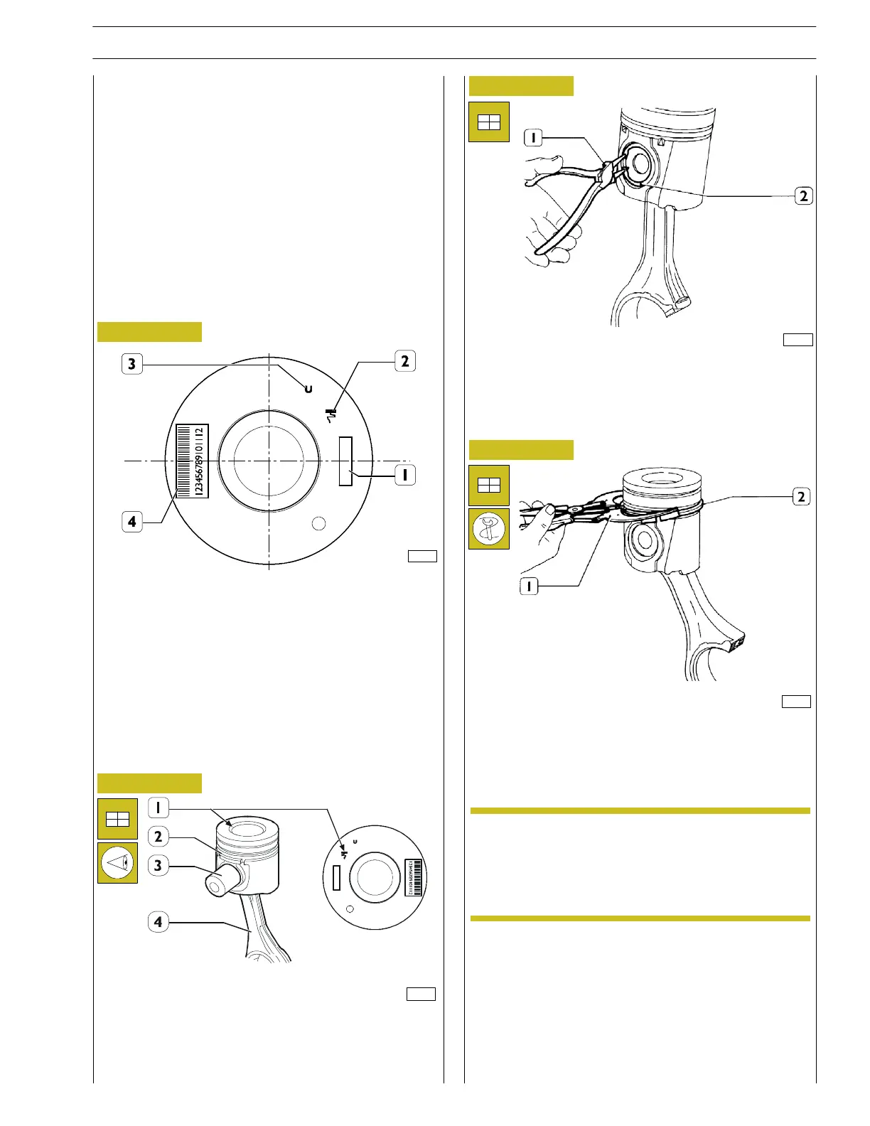
The following references are marked on the piston crown:
1. Spare part number and modification number;
2. Symbol indicating the installation mark for the piston
inside the cylinder liner; it should be turned towards the
flywheel side (the symbol (2) may be represented as
illustrated in the figure or with an arrow, in accordance
with production requirements);
3. Stamping proving 1st slot insert inspection;
4. Date of manufacture
Figure 45
128139
Throughout the pin (3), connect the piston (2) to the
connecting rod (4) following the indication of the reference
arrow (1) to correctly fixing the piston (2) into the cylinder
barrel, also taking into consideration the numbers (5) printed
on the connecting rod (4), as shown in the figure.
126312
126311
Figure 46
Figure 47
Fit the pin snap rings (2).
Snap ring assembly
Use the pincers 99360183 (1) to fit the snap fasteners (2) to
the piston.
The snap rings must be fitted with ”TOP” marking upwards.
Furthermore, ring opening must be misaligned by 120º.
The spare sn ap rings are available in the following
sizes:
-standard;
- oversize by 0.4 mm.
NOTE
SECTION 4 - MECHANICAL OVERHAUL
23
F32 SERIES
Pri nt P2D32F005 E Base - April 2009