8
SECTION 2 - SUPPLY
F32 SERIES
Base - April 2009 Prin t P2D 32F005 E
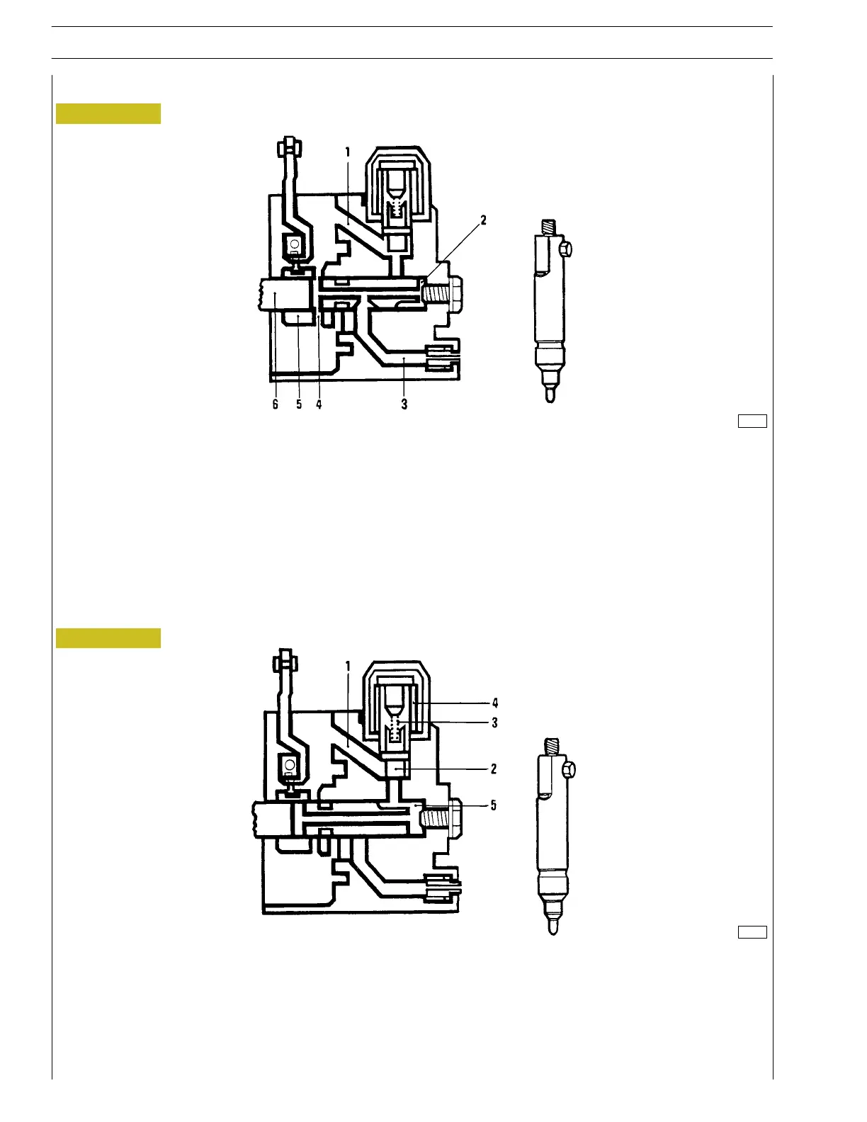
End of delivery phase
Figure 7
119417
1. Fuel feed pipe - 2. Compression chamber - 3. Fuel delivery pipe - 4. End of delivery pipe -
5. Cursor - 6. Distributor piston.
The distributor piston (6) moving towards the T.D.C. connects the high pressure inner chamber to the pipe (1), thereby
establishing pressure balance between the distributor piston inner chamber, the injectors’ delivery pipe and the pump interior.
Since such pressure is lower than the one required to start the injector, end of delivery will be determined.
Engine stop
Figure 8
119418
1. Fuel feed pipe - 2. Mobile cap - 3. Spring - 4. Solenoid valve - 5. Compression chamber.
Engine stop is provoked cutting out the starter contact.
The electric flux to th e solenoid valve (4) is cut out. The solenoid valve, throughout its spring (3), drives the mobile cap t o the
end of stroke (2) and the mobile cap obstructs the fuel feed pipe (1).