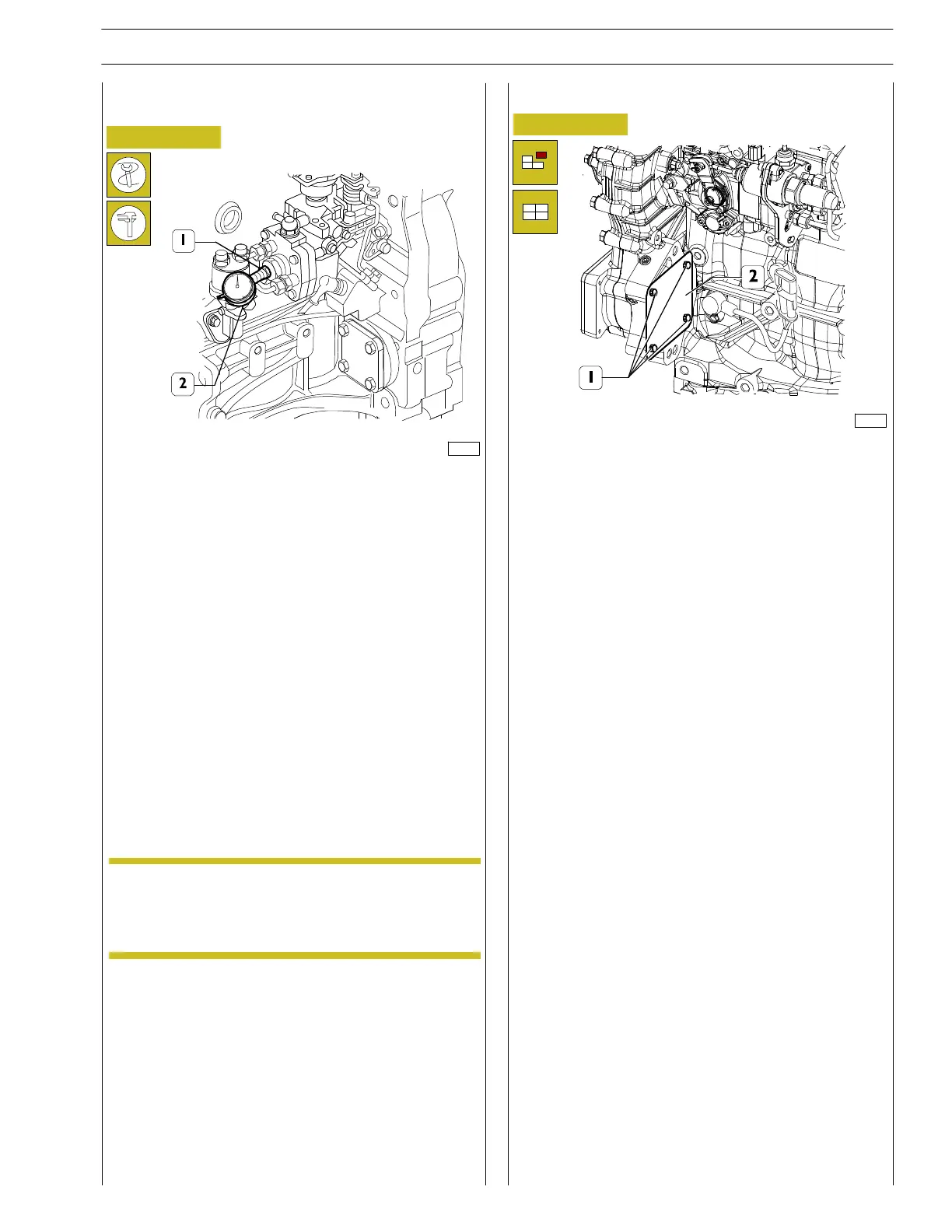
With injection pump inserted in its housing and retainin g
screws released, fit dial gage 99395603 (2) and dial gage
holder 99395100 (1), preloading rod by 2,5 mm.
- Rotat e crankshaft and move from 1st cylin der at TDC to
end of compression phase condition.
- Reset dial gage and rotate crankshaft in opposite
direction to return to 1st cylinder at TOD during
compression. In this position, the dial gage fitted on
pump must display values below:
0.88 ± 0.05 mm (61 kW engin es);
0.76 ± 0.05 mm (55 and 65 kW engines).
- After these conditions have been verified, lock the pump
in place by tightening the relevant nuts onto the
corresponding torque. On the other hand, if these
conditions are not verified, you should contact the
specialised assistance service, as it will not be possible t o
rotate the pump for reasons linked to the TIER 3
standards.
Injection pump static advance control on
engine at cylinder 1 TDC
87720
Figure 88 (Demonstration)
Figure 89
128133
For the engines w ith power takeoff, operate as follows:
- loosen the 2 fastening screws (1) and remove the cover
(2).
- Insert th e device utilizing the fast ening points available.
Power takeoff
The advance control should be performed while
the KSB is hot, i.e. previously excited, in order to
cancel out the advance with which the cold pump
operates.
NOTE
SECTION 3 - INDUSTRIAL APPLICATION
33
F32 SERIES
Pri nt P2D32F005 E Base - April 2009