70200
70201
Figure 48
Figure 49
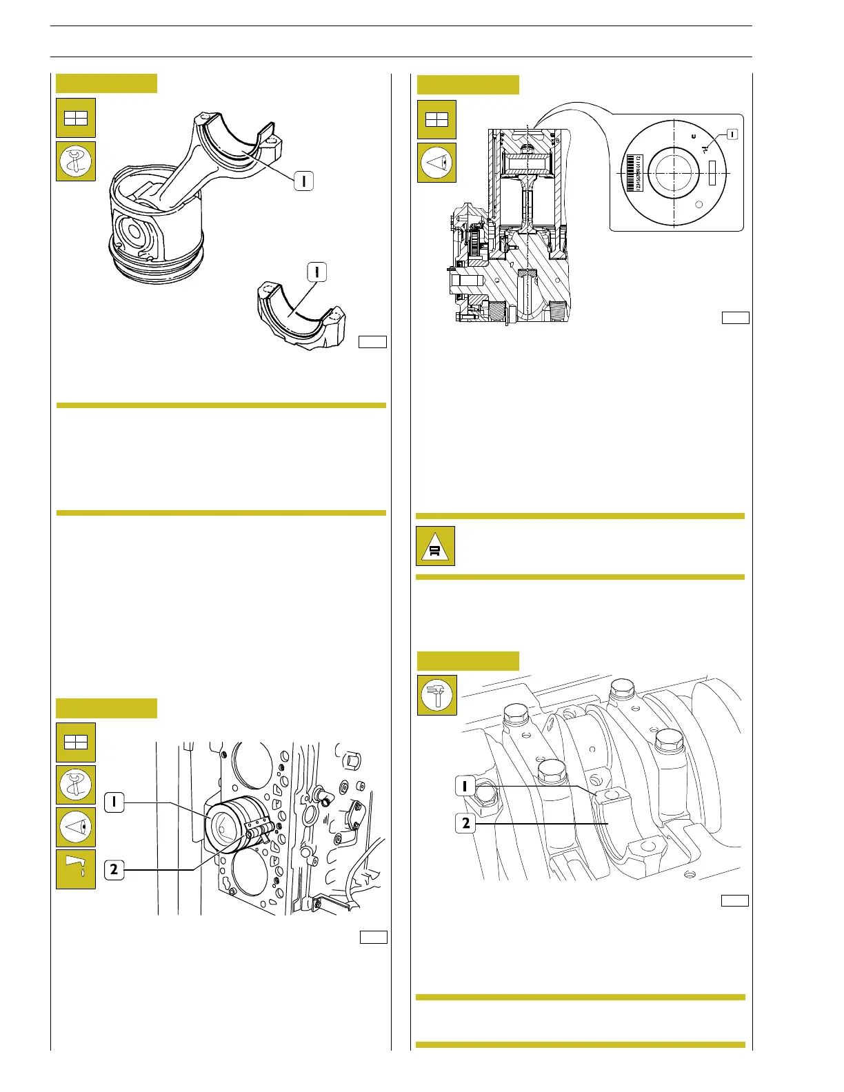
Fit the half bearings (1) on the connecting rod and cap.
Lubricate t h e pistons, the snap pins and the cylinder barrel
interior.
Using the band 99360605 (2), fit t he c onnecting rod-piston
unit (1) into the cylinder barrel, checking that :
- the number of each connecting rod corresponds to the
coupling cap number.
Fitting connecting rod-piston assembly into
cylinder barrels
if it is not necessary to replace the big end bearings,
reassemble the existing ones in the same order and
position they were before disassembly.
Do not adapt the half bearings.
NOTE
119566
128170
Figure 50
Figure 51
SCHEME FOR CORRECTLY FIXING THE
CONNECTING ROD-PISTON UNIT INTO THE
HOLLOW
- The snap rings’ openings must be misaligned by 120º;
- all the connecting rod/piston units must have the same
weight;
- the en gin e drive sh aft sign (1) printed on the piston
crown must be turned towards the flywheel while the
notch on the piston shield must match the oil n oz z les’
position.
Connecting rod caps fitting
- carefully c lean the parts eliminating any oil residuals;
- fit the connecting rod caps (1) and the relevant half
bearings (2).
Always use new screws in phase of assembly.NOTE
Warning! The connectin g rod must n o t collide with
the cy lin der wall.
24
SECTION 4 - MECHANICAL OVERHAUL
F32 SERIES
Base - April 2009 Pri nt P2D32F005 E