Figure 11
THERMOSTAT DIAGRAM
Working system
When the engine is cool, water output from the front part of the cylinder head flows into an inlet containing the thermostat, which
cuts out water circulation to the radiator. This way, water circulation will only be possible in the pump-engine circuit, insofar allowing
engine heat-up quickly. The thermostat valve starts opening at nearly 80 ˚C, allowing water circulation into the radiator and also
obstructing direct return towards the engine. Check the thermostat efficiency and replace it in case of doubtful functioning.
1. Stroke starts at 79˚ ±2˚C
2. 7 mm stroke at 94˚±2˚C
119412
120047
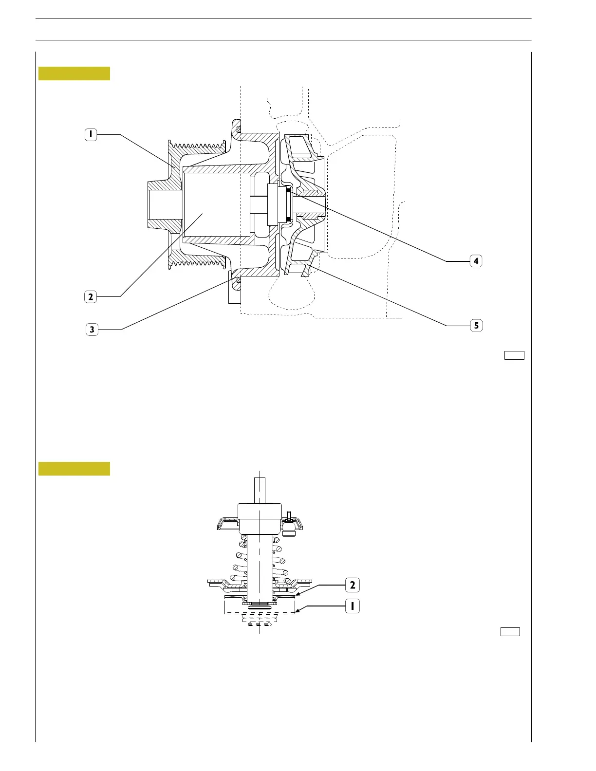
Figure 12
The water pump is a centrifugal blade turbine type pump. The pump’s bearing (2) is connected to the impeller’s shaft as a whole.
Water tight between the pump unit (3) and the shaft (2) is ensured by the sheath (4).
WATER PUMP SECTION
1. Hub - 2. Shaft with bearing - 3. Pump unit - 4. Sheath - 5. Impeller.
ATER PUMP
THERMOSTAT
12
SECTION 1 - GENERAL SPECIFICATIONS
F32 SERIES
Base - April 2009 Print P2D32F005 E