SECTION 2 - SUPPLY
7
F32 SERIES
Pri nt P2D32F005 E Base - April 2009
WORKING SYSTEM DESCRIPTION
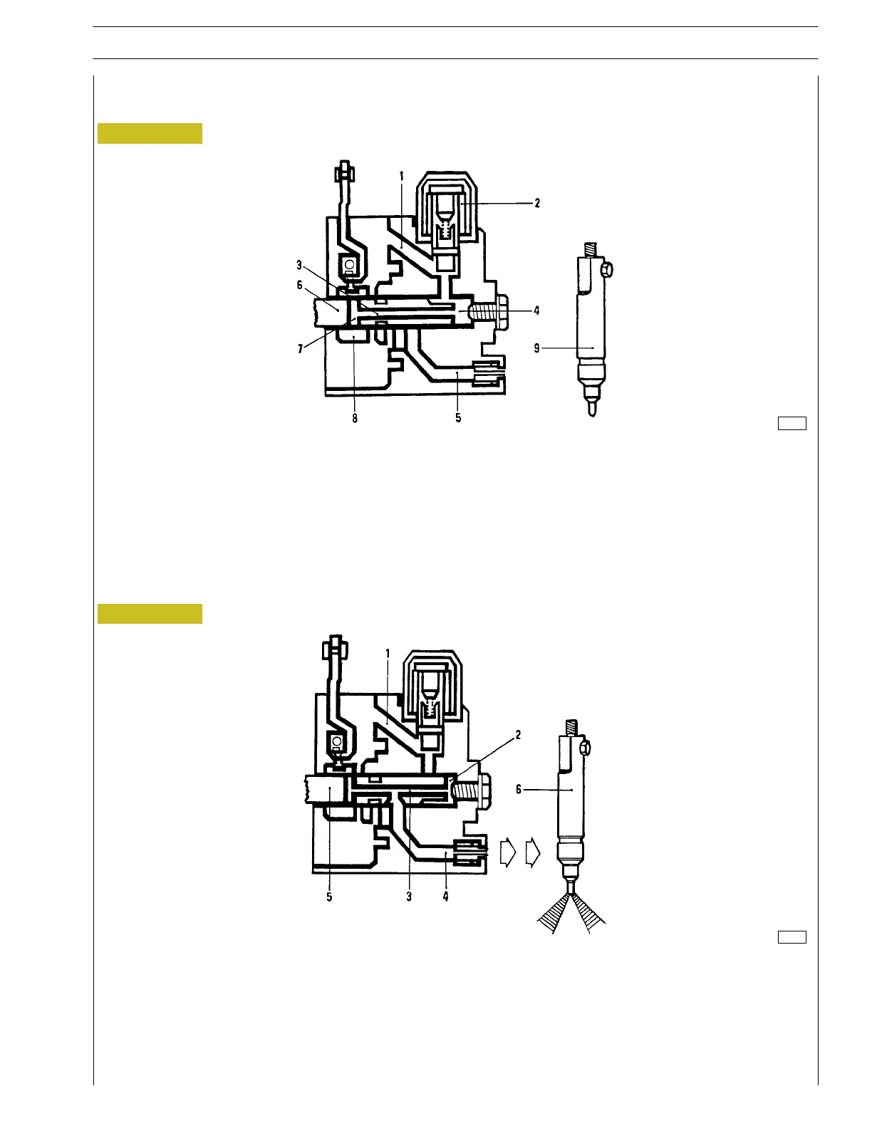
Supply phase
Figure 5
119415
1. Fuel supply pipe - 2. Solenoid valve - 3. Axial groove - 4. Compression chamber - 5. Fuel delivery pipe from pump to
injectors - 6. Distributor piston - 7. E n d of delivery port - 8. Cursor - 9. Injector.
The distributor piston (6) is at B.D.C. an d the c u rsor (8) c loses the delivery port (7). The fu el is delivered to th e compression
chamber (4) through the feed pipe (1) which is kept open by the solenoid valve (2).
Delivery phase
Figure 6
119416
1. Fuel feed pipe - 2. Compression chamber - 3. Distributor piston inner pipe
4. Fuel delivery pipe from pump t o injector - 5. Distributor piston - 6. Injec t or.
The distributor piston (5) driven by the cam disk, goes up to the T.D.C. and simultaneously rotates on its own axle. The
combination of th e two motions determines the closure of the fuel feed pipe (1) as well as the fuel c o mpression within the
chamber (2). The distributor piston inner pipe (5) is connected to the feed pipe (4) thus enabling fuel delivery to the injec t ors
(6).