119720
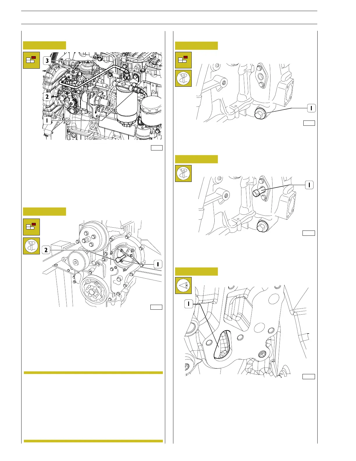
Figure 4
- Remove the L.D.A. pipe. Remove the fast clutch fuel
pipes from the priming pump to the filter (1) and from
the filter to the ignition pump (2), then fit the specially
provided caps to the pipes, the pumps and the filter.
Unscrew the screws (3), fastening the fuel ignition pipes
and remove them.
119106
Figure 5
- Unscrew the pump fastening screws on the rear part of
the gear cover. To disassemble the pump, fit tool
99340025 to th e pump wheel and fix it with the three
screws (1).
Using the specially provided wrench, slowly tighten the
screw (2) holding th e rear part of the pump removing
the pump completely.
Before pump disassembly, use the
speciallyprovided tool (99360612), lock the engine
into theposition corresponding to T.D.C. for
cylinder 1. Now block with the specific system the
pump shaft; this way the pump should be timed, so
that when refitting (if no maintenance intervention
is required on it) no adjustment is necessary.
NOTE
For all engines
Figure 6
Cylinder 1 T.D.C. search
Position the engine drive shaft at T.D.C. of cylinder 1 rotating
the flywheel un t il achieving t h e following c on ditions:
- the notch (1) is visible from the in spection hole;
- to ol 99360612 should be fitted through the carter into
the port on the flywheel.
Remove tools and tighten the previously loosened plate
screws.
124497
Figure 7
- Fit tool (1) 99360330 to flywh eel housing to rotate the
flywheel (must be used with a suitable wrench).
Figure 8
- Loosen the screws of the plate in which tool 99360612
(1) is to be fitted.
132006
133189
8
SECTION 3 - INDUSTRIAL APPLICATION
F32 SERIES
Base - April 2009 Prin t P2D 32F005 E
zl