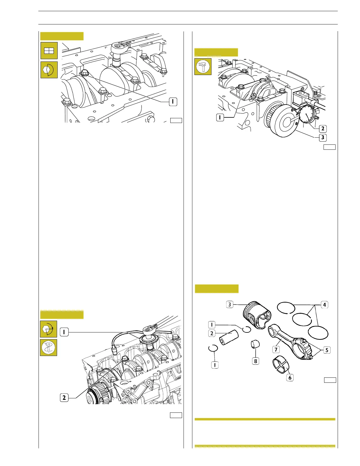
The check of the shoulder clearance is performed with a
magnetic based comparator (2) placed on the engine shaft
(3) as in dicated in the figure.
If the clearanc e is above the one prescribed replace the
semi-c rankshaft bearings of the thrust hold rear support next
to the last (1) and check again the clearance between the
engine shaft pins and the semi-crankshaft bearings.
119559
70190
70191
Figure 29
Figure 30
Figure 31
- 3
rd
phase using tool 99395216 (1) fitted as shown in t he
figure and further tighten the screws (2) by 90º angle.
CONNECTING ROD-PISTON UNIT COMPONENTS
1. Grommets. - 2. Pin. - 3. Piston. - 4. Snap rings. - 5.
Screws - 6. Half bearings. - 7. Connecting rod. - 8. Bush.
α
Checking output shaft shoulder clearance
The spare pistons are supplied with standard
dimensions or oversize by 0.4 mm.
CONNECTING ROD — PISTON ASSEMBLY
70187
Tighten the pre-lubricated screws (1) an d tighten them in
three subsequent phases:
- 1
st
phase with torque wrench setting at 50 ± 2.5 Nm.
- 2
nd
with torque wrench setting at 80 ± 4 Nm.
Figure 32
NOTE
SECTION 4 - MECHANICAL OVERHAUL
19
F32 SERIES
Pri nt P2D32F005 E Base - April 2009
Revi - 12.2012