119121
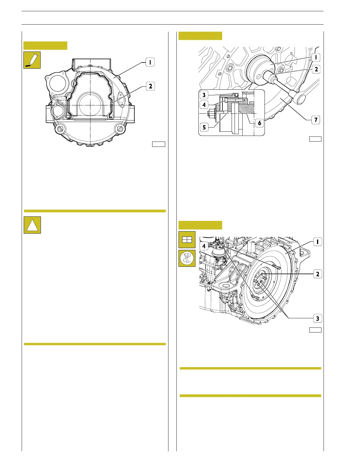
Figure 26
Figure 27
- Fit the specific tool 99346259 (5) to the rear shank (6)
oftheenginedriveshaft,fixitwiththescrews(4)and
spline the new grommet (3) thereon.
- Position part (1) on part (5), tighten the screw nut (2)
until the grommet has been fitted (3) into the flywheel
casing (7).
It is absolutely necessary to c lean the su rface to be
sealed in order to obtain perfect tightness.
Apply LOCTITE 5999 sealer on th e gearcase in
order to form a sealing bead of a few mm.
The sealing bead must be homogeneous (no lumps),
free of air bubbles, thinner areas and gaps.
Any imperfection must be corrected as soon as
possible.
Avoid the excess of sealer: too much sealing material
would leak and pour out on both sides of the joint
parts and, as a consequence, obstruct the passage of
the lubricant.
After having applied the sealer, the parts must be
joined within 10 minutes.
Rear side component assembly
SCHEME FOR THE APPLIANCE OF LOCTITE 5999
SEALER ON THE TIMING GEARCASE
- Accurately clean the timing gearcase (1) and the engine
basement.
133190
!
Figure 28
- Screwtwohooksoreyeboltsontheflywheel(1)
through the ports (4).
- By means of a hoister, draw the flywheel up to its housing
inside the casing.
119113
Flywheel assembly
- Screw two pins (2) of appropriate length into the shaft’s
ports (3) and, using them as a guide, duly fit the engine
flywheel (1) into its casing.
- Tighten the screws fastening the engine flywheel to the
engine drive shaft. Fit the tool 99360330 to the flywheel
casing in order to lock the engine flywheel rotation.
The flywheel has a reference dowel that couples
with the relevant seat on the box.
NOTE
14
SECTION 3 - INDUSTRIAL APPLICATION
F32 SERIES
Base - April 2009 Prin t P2D 32F005 E