75750
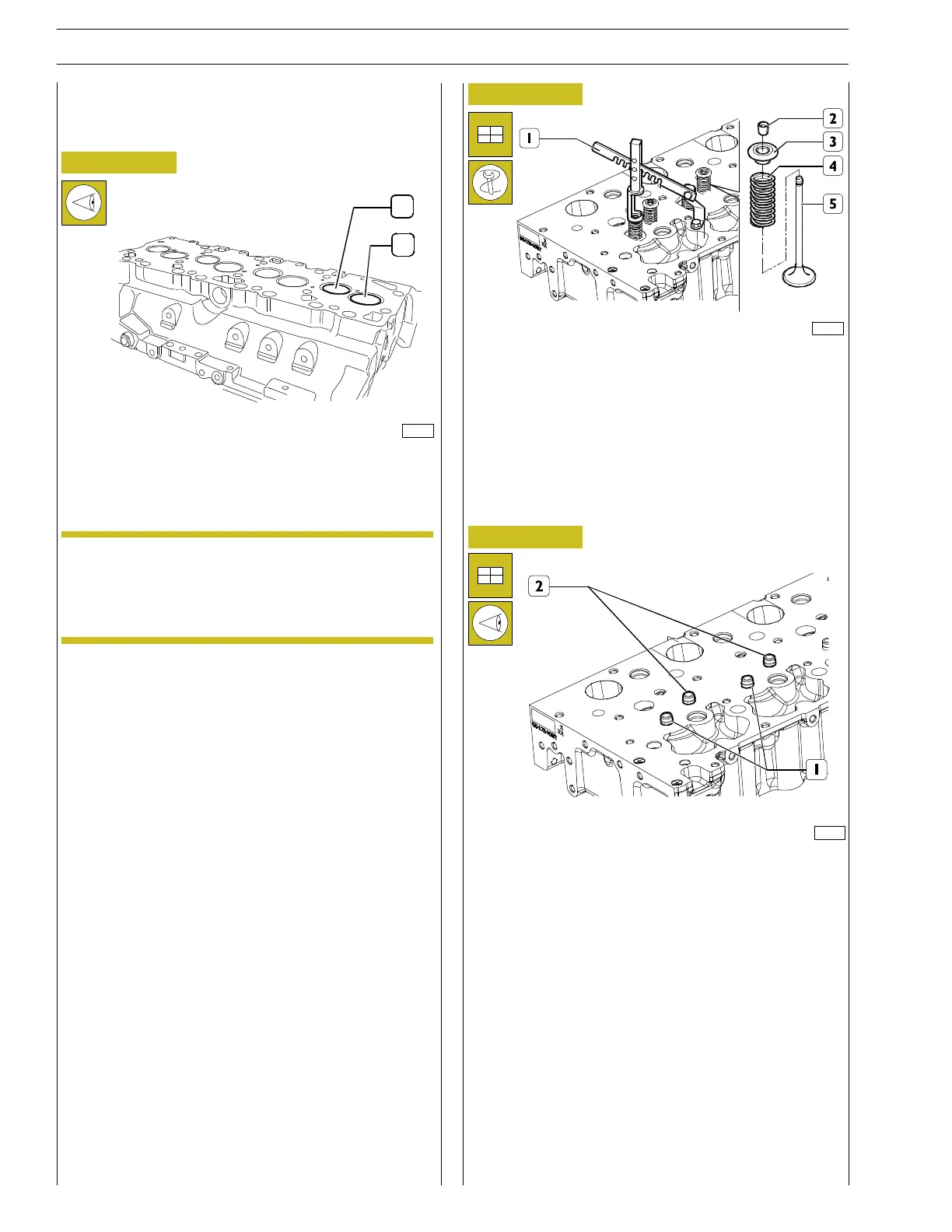
Figure 54
The intake valves (1) and exhaust valves (2) have different
head diameter.
Number the valves before removing them from the
cylin der head in order to be able to reassemble
them in the same order in case replacement is not
necessary.
A = intake side
CYLINDER HEAD
Valve disassembly
Valve disassembly must be executed us ing tool 99360268 (1)
to slightly press the plate (3) so that, compressing the spring
(4), it is possible to remove the half cone (2). Then remove
the plate (3) and the spring (4).
Repeat the o peration in correspondence of each valve.
Turn the cylinder head upside down and withdraw the valves
(5).
119567
119568
Figure 55
Figure 56
Remove the grommets (1 and 2) from their valve guides.
1
2
A
NOTE
26
SECTION 4 - MECHANICAL OVERHAUL
F32 SERIES
Base - April 2009 Pri nt P2D32F005 E