119409
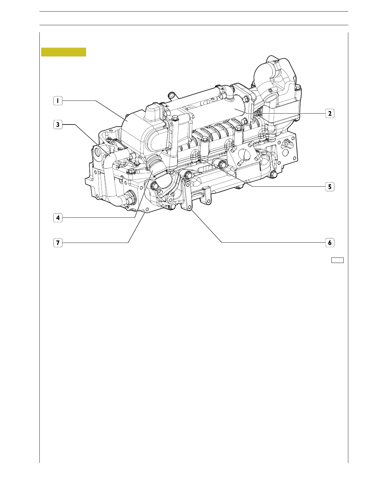
Figure 15
Working system
The EGR system fitted in between the exhaust manifold and the intake manifold allows partial exhaust gas recovery into the engine
cylinders after having been cooled throughout a heat exchanger. This way the combustion temperature maximum values,
responsible of the formation of Nitrogen oxides (NOx) can be reduced. Hence, reducing the aforesaid temperatures by decreasing
the concentration of oxygen in the combustion chamber, the EGR system efficiently controls NOx emissions.
As shown in the figure, throughout pipe (4) the exhaust gas will be conveyed through the exhaust manifold to the valve unit (1).
If the control unit enables the valve, the exhaust gas will be conveyed to the heat exchanger (2) where it will be cooled throughout
the engine cooling liquid system which controls the cooling liquid recirculation through the water pipe (3) and the valve unit (1)
(cooling the valve as well) from the engine head to the heat exchanger. The cooled exhaust gas will be further conveyed from the
heat exchanger to the intake manifold.
1. Valve unit - 2. Heat exchanger - 3. Water pipe - 4. Exhaust gas pipe - 5. Intake manifold
6. Exhaust manifold - 7. Engine head.
External E.G.R. system
for F5CE5454 en
ines
SECTION 1 - GENERAL SPECIFICATIONS
15
F32 SERIES
Print P2D32F005 E Base - April 2009