Figure 85
- Assemble the pump pre-set in its hou sing on the engine,
fitting the shaft into the gear port (not provided with
wrench).
- Tighten the fixing nuts (1) locking the pump flange in the
slot c ent re.
- On the timing side, throughout the specially appointed
port, fit the washer and screw up the fixing nut (2) to the
pump shaft. Lock the nut to the prescribed pair.
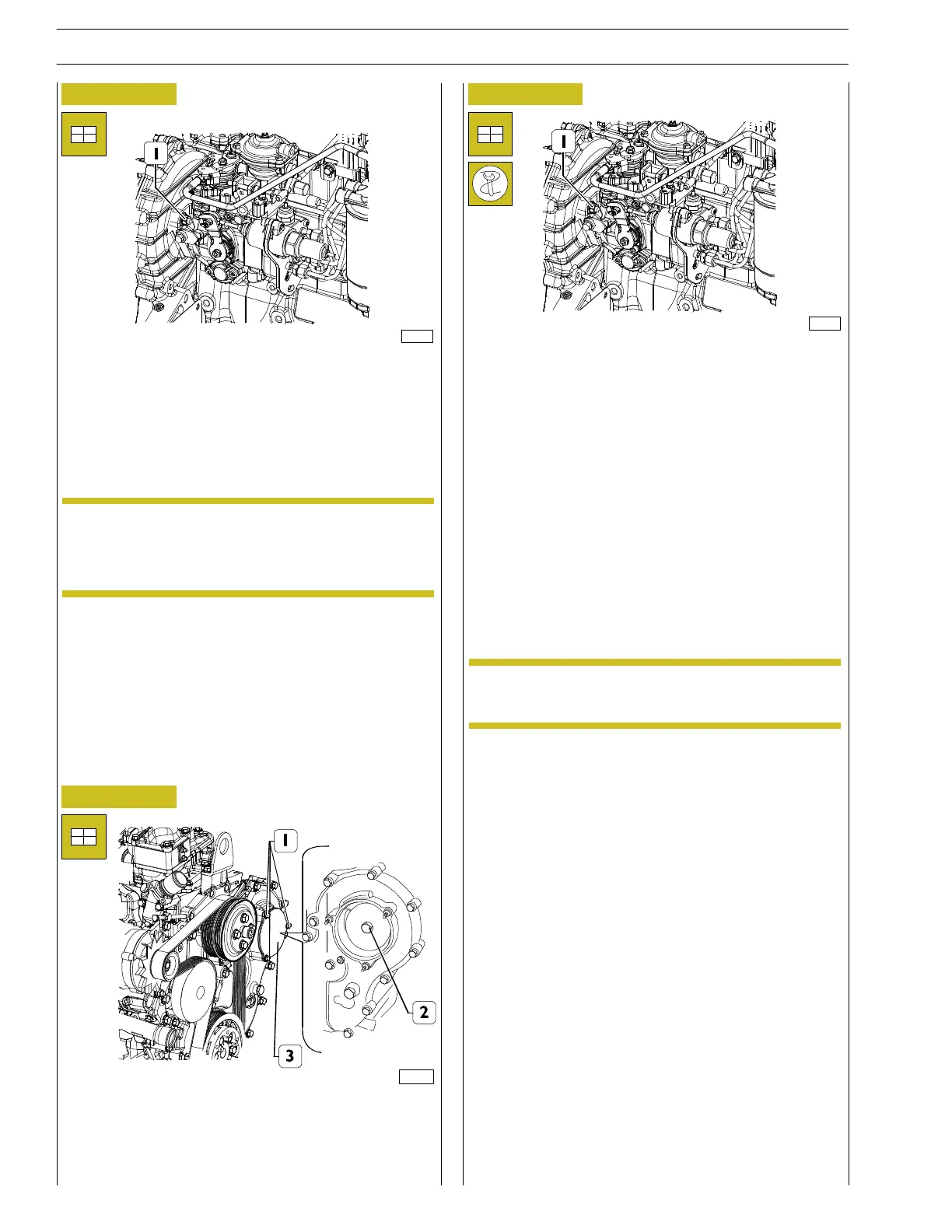
Figure 86
Figure 87
- Loosen screw (1) that prevents pump shaft rotation and
insert spacer (2). Tighten screw (1)so that it locks spacer
(2): in th is way the supply pump shaft will be able to
rotate freely.
- Assemble the cover (3, Figure 86) including gasket and
tighten the screws (1, Figure 86).
- Tighten the previously loosened plate screws.
- Connect all pipelines (from pumping elements to injectors,
bleeding recovery pipes from injectors to pump, LDA
pipeline and feed provided by priming pump).
- Connect electrical connections to electro-magnets on the
hydraulic head and on KSB.
The gasket removed during pump disassembly shall
not be utilised again .
Always use original spare parts.
If the pump has been removed with the engine
mounted, connect the accelerator cable, if present
in the application.
NOTE
NOTE
128132
124487
128132
32
SECTION 3 - INDUSTRIAL APPLICATION
F32 SERIES
Base - April 2009 Prin t P2D 32F005 E