- From timing side, remove the cover (3) loosening the
screws (1) in order to have access to the union fixing nut
(2) to the pump driving gear.
- Loosen the fixing nu t (2) and remove the relating
washer.
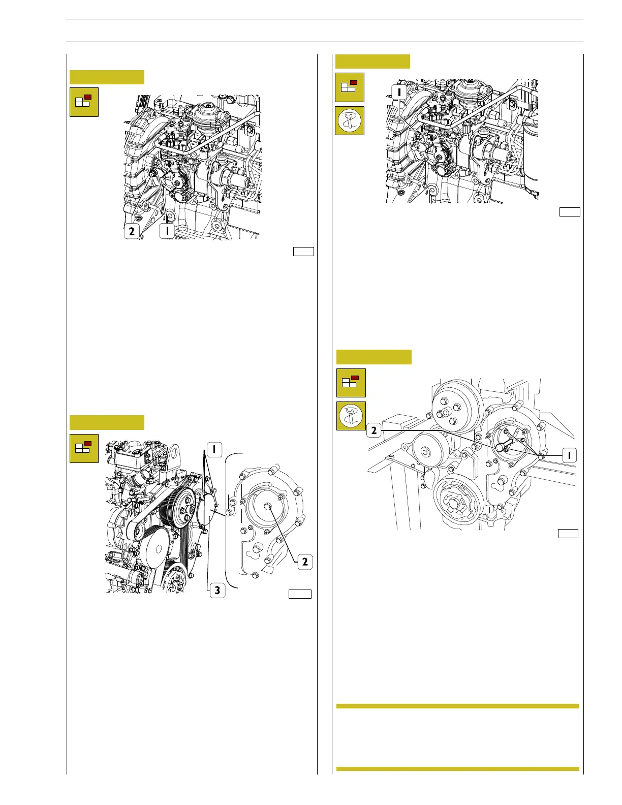
Figure 81
- Unscrew the side screw that locks the pump shaft
partially (2) a nd remove spacer (1). This must be kept on
a side (we recommend to fix it on the pump with a wire
or a clip).
- Tighten the lateral screw (2) blocking rotation of the
pump shaft.
Figure 82
Figure 83
128132
- From the pump side, loosen the fixing nu ts (1) without
removing them in order to enable moving the pump
backwards using 99340025 extractor.
Hold the pump driving gear to avoid interference
or crawling during timing gear rotation.
128131
BOSCHVE4/12FPump
NOTE
124487
119106
Figure 84
- Assemble the 99340025 (2) extractor throughout the
three threaded ports (1) and withdraw the gear from the
pump shaft.
- Properly hold the feed pump and loosen c ompletely the
fixing nuts.
- Withdraw the pump from the studs, together with the
gasket.
When the supply pump is to be assembled on the engine the
P.M.S. conditions at compression end stage c ylinder No. 1
must be carried out .
SECTION 3 - INDUSTRIAL APPLICATION
31
F32 SERIES
Pri nt P2D32F005 E Base - April 2009