4
Initialisation of the controller
1.
ME: Mode Entry Modules
1.1.
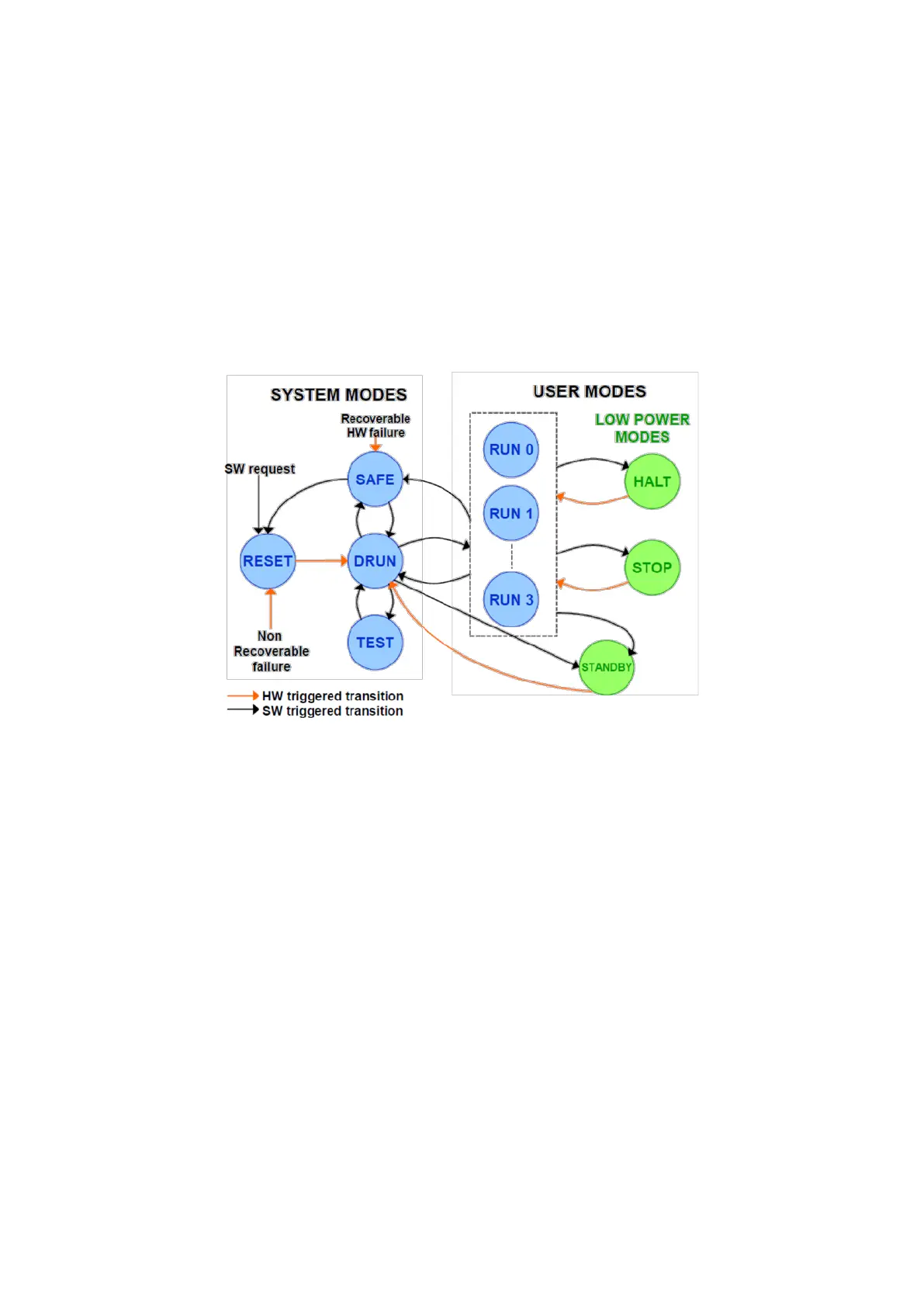
This module controls the device modes, their settings and the transitions between them. On
Figure 1, you can find different modes that are availcontroller. They have to be
initialised properly, after reset, in order to get the right configuration for the system.
Figure 1 : MC_ME Mode Diagram (Freescale Lecture)
In this paragraph we will quickly explain RESET, DRUN, SAFE, TEST, RUN 0...3 modes, which are
needed for embedded applications. See Wakeup Events chapter for more information about
STANDBY and STOP modes.
System Modes
o RESET: This state is active after a system reset or a non-recoverable failure.
The device leaves this state once the reset sequence that initialises the chip
and power is completed. The system clock is set to the internal 16MHz RC
oscillator.
o DRUN: This is the entry mode of the software which can control the flash
memories, configure clocks, user modes before going into a user mode. This
is the first thing to be done in “main” procedure (Default RUN).
o SAFE: The device goes into this state once a recoverable hardware failure has
occurred. After handling the failure the system goes in to the DRUN mode,
reinitialising the software.
o TEST: This mode allows software to do on-chip test routines with peripheral
modules, RAM etc.
User Modes
o RUN0…3: This is where the software runs; these four RUN modes can be
configured with different clock and power settings.