LFDIV is set using two registers: LINIBRR, the integer part of LFDIV and LINFBRR where the
fractional part is encoded. LINIBRR contains the 13-bit field, DIV_M, which sets a mantissa
between 1 and 8191. If DIV_M is set to 0, then the LINFlex clock is disabled. LINFBRR register
contains a 4-bit DIV_F field where DIV_F = 16× _
(
LFDIV
)
.
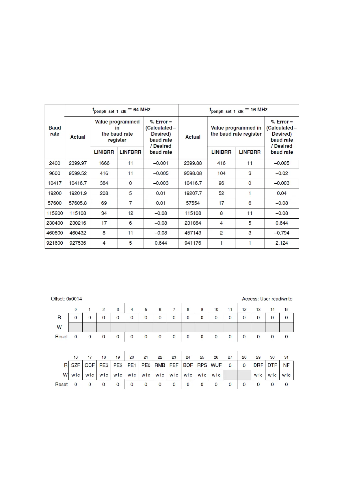
There will be some error in baud rate values and an error over 1% - 1.5% should be avoided if
the system clocks are imprecise.
Figure 101 : Error calculation for programmed baud-rates (R.M. Rev8 –Table 21-1)
Status Registers and Interrupt Configuration
Figure 102 : UART Mode Status Register (R.M. Rev8 –Fig. 21-11)
The UART mode Status Register (UARTSR) contains all the flags that signal different kind of
events about the module, and some of them can raise interrupts.