CAN controllers have a system clock that allow them to process registers, set outputs and read
inputs. The period duration of this clock is called the time quantum
and used as a base to
transmit and receive frames. A bit-time is built of four time segments, each defined by an integer
number of time quantum. These segments allow the receiver to synchronise before sampling a
bit, minimising chances of misread data. The bit time also determines the bit-rate of the
network.
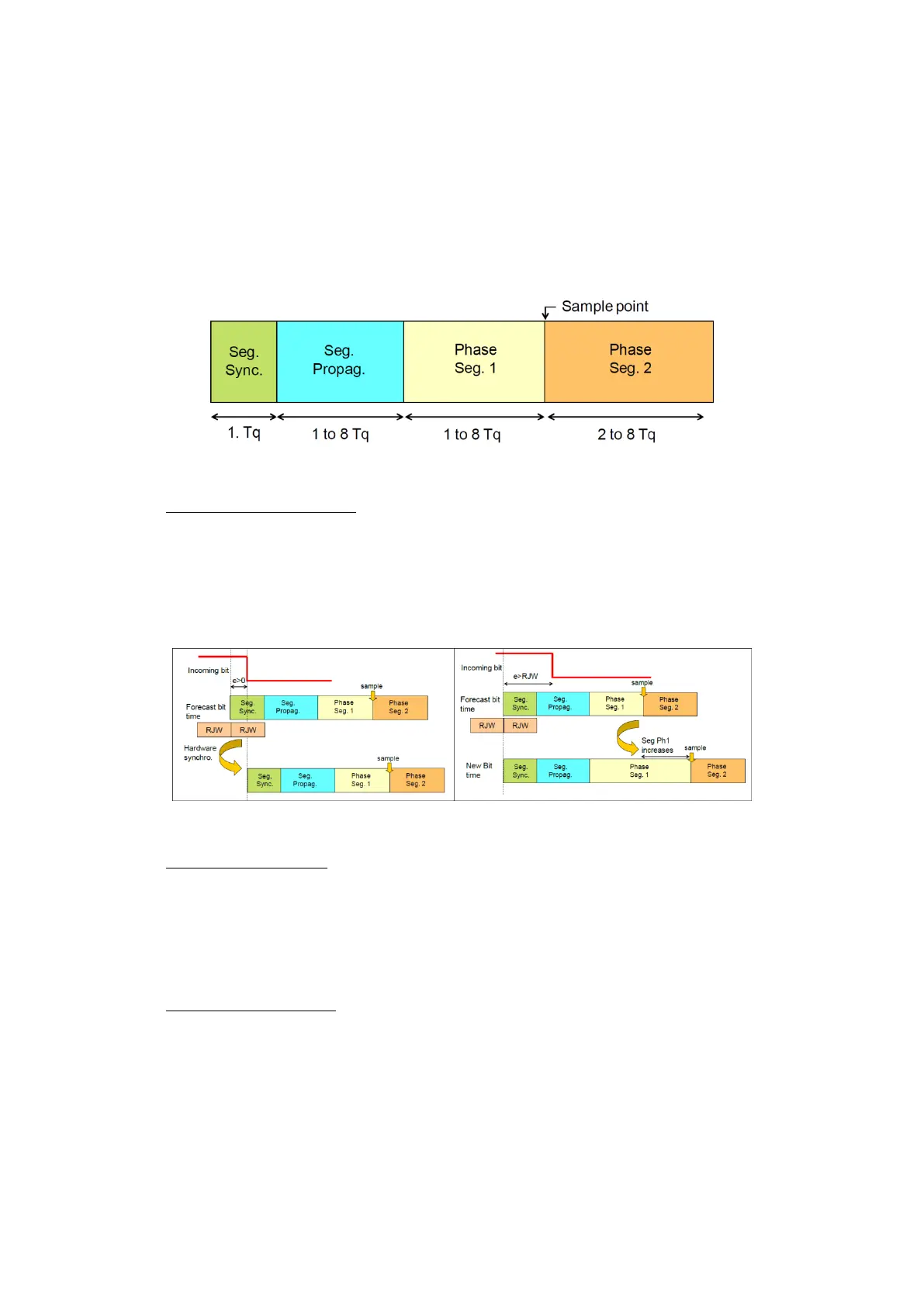
Figure 115: Bit-time structure
Synchronisation segment: always equal to one time quantum, rising/falling edge of the
incoming bit has to be before a forecast time of this segment. In practice this rarely
happens, so the standard tries different way to synchronise by changing the length of
different segments, or delaying them, depending on a value called
RJW(Resynchronization jump width). These methods are illustrated on the following
figure.
Figure 116: Bit-time resynchronisation methods
Propagation segment: Takes in account the delay due to the propagation speed of the
CAN signals. CAN standard suggests considering the worst case situation where a device
emits recessive bit and just before this bit reaches its destination, the other device emits
a dominant bit. Therefore the total delay becomes the round trip time of the signal
2*(2.
+ 2.
+
). Propagation segment has to be
greater than this value.
Phase segments 1&2: Phase segment 2 should not be shorter than CAN controller’s
information processing time(IPT 2
usually) and depending on number of quanta in
the bit time we can have Phase_Seg_1 = Phase_Seg_2 or Phase_Seg_2 = Phase_Seg_1 + 1;
Depending on these values, a CAN bus’ efficiency can change a lot, an effective method for
calculating these values is:
Finding the total delay explained above, either with device datasheet or measurements.
Selecting a frequency for CAN Controller clock and a bit-rate meeting the specifications.