All the fields of this register can be cleared by writing ‘1’, and they are:
NF: Noise Flag, set when hardware detects noise on a receive channel.
DTF: Data Transmission Completed, set by the hardware when the number of bytes
programmed in TDFL have been transmitted.
DRF: Data Reception Completed, set by the hardware when the number of bytes
programmed in RDFL have been received.
WUF: Wake-up Flag, set when a reception is detected while the module is in sleep mode
and auto wakeup is enabled.
RPS: Receive Pin State, reflects the current status of LINRX for diagnostic.
BOF: Buffer Overrun Flag, this bit is set when the receive buffer is full and new data is
being received (discarded or not).
FEF: Framing Error Flag, this bit is set when a framing error is detected (stop or start bit
misplaced).
RMB: Release Message Buffer, this bit is set when there is data in the receive buffer ready
to be read.
PEx (x=0…3), Parity Error Flag, when set, there is a parity error in the received byte x
(in the buffer).
OCF: Output Compare Flag, this flag is related to the LINFlex module internal counter.
Not explained here.
SZF: Stuck at Zero Flag, this bit is set by hardware when the bus is dominant (at 0) for
over a 100-bit time.
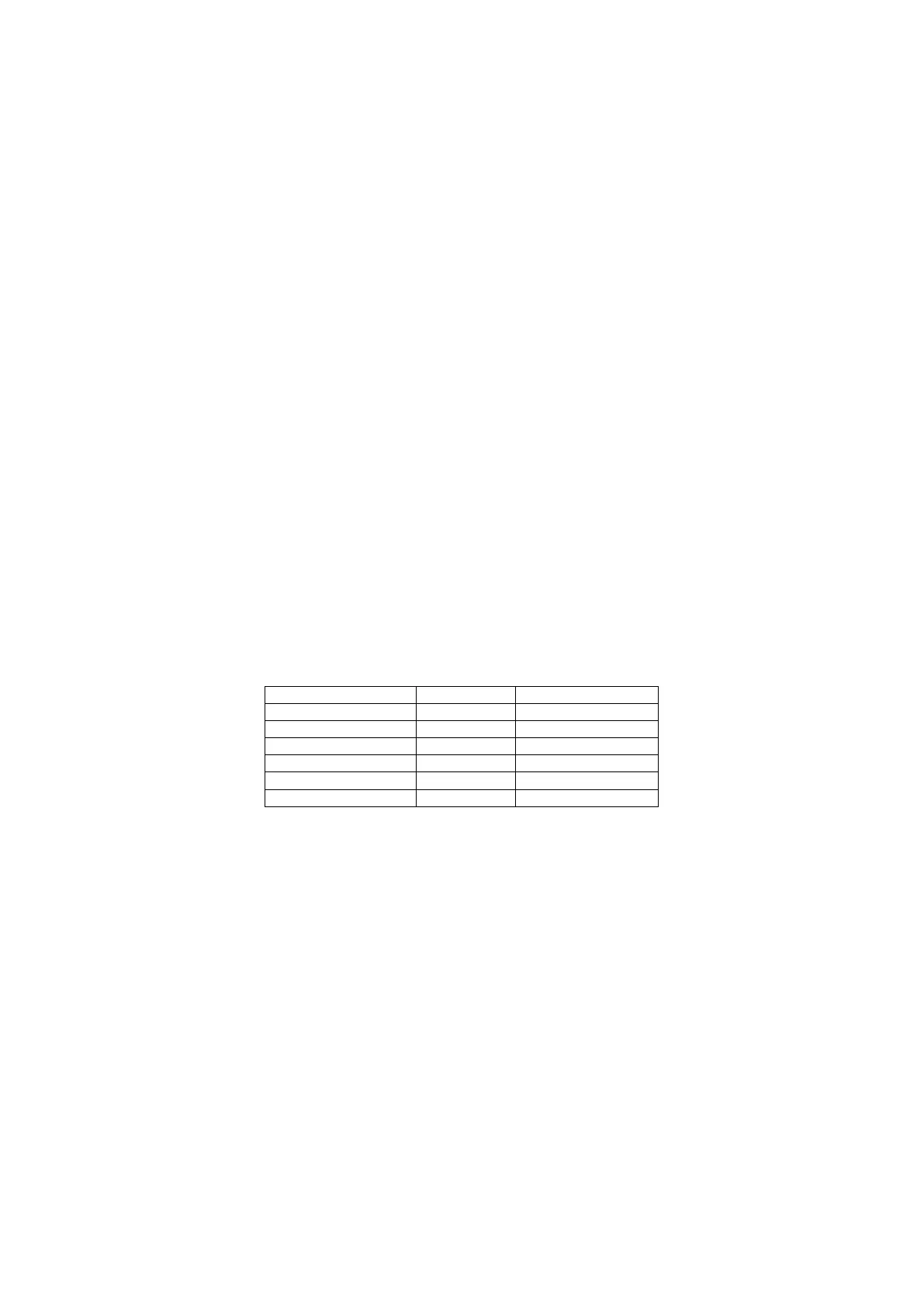
Some interrupts are related to these flags and they can be enabled using LIN interrupt enable
register. Here is the list of enable interrupt bits related to UART flags:
There are only three ISR for each LINFlex module, ERR, RXI and TXI. They are shown on the
table above.
There are two buffer data register Buffer data register LSB (BDRL) and Buffer data register MSB
(BDRM). BDRL contains 4 bytes, from DATA0 to DATA3, and BDRM has DATA4 to DATA7. These
register are used as both receive and transmit in LIN mode, but in UART mode, BDRL is the
transmission buffer and BDRM is the receive buffer.
These buffers might not be fully used depending on the specified size on TDFL and RDFL.