6
Example for configuring RUN0:
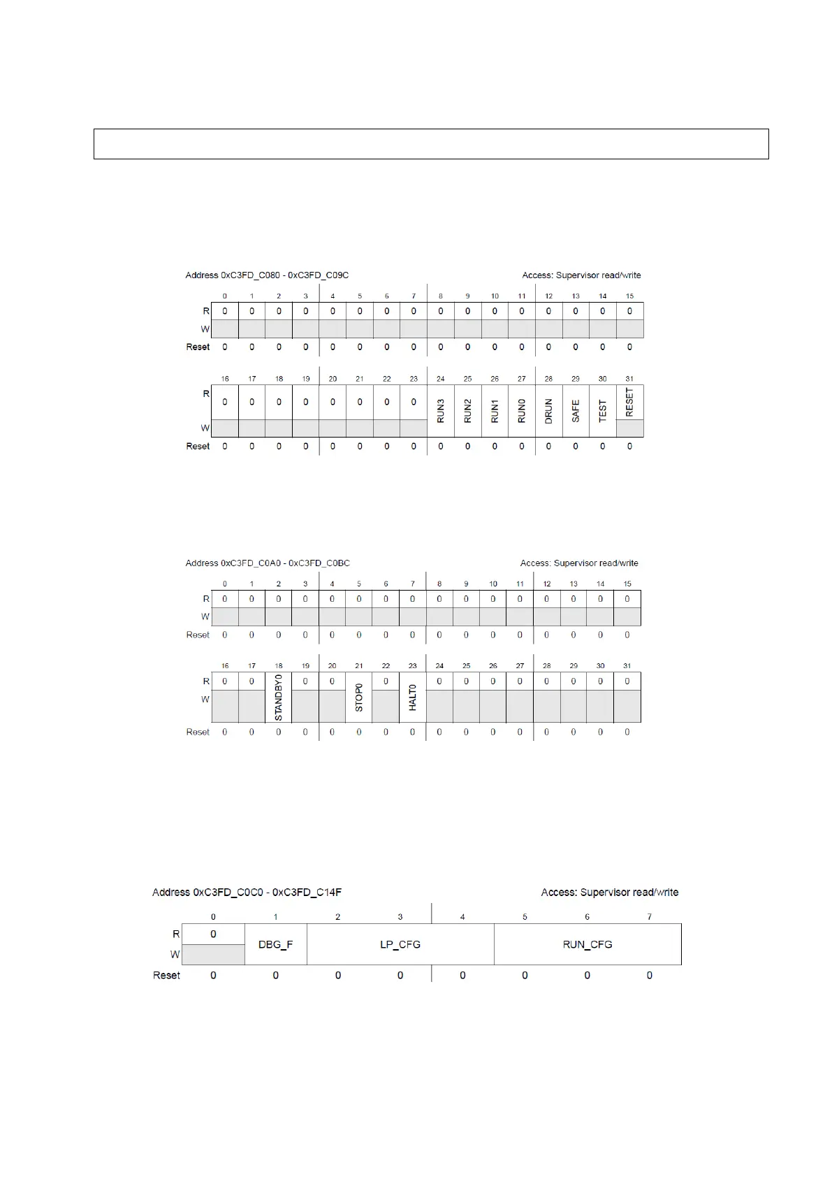
Having configured different modes, we possess 8 different registers that allow us to configure a
peripheral to only run on a set of specific mode. These registers are called Run Peripheral
Configuration Registers (RUNPC[0] to RUNPC[7]).
Figure 4 : Run Peripheral Configuration Registers (Reference Manual Rev8 – Fig. 8-21)
You may notice that STANDBY, HALT and STOP cannot be selected using this register, you’ll
need to use Low Power Peripheral Configuration registers (LPPC[0] to LPPC[7]).
Figure 5 : Low Power Peripheral Configuration Registers (Reference Manual Rev8 – Fig. 8-22)
Once all the possible modes have been selected using these 8+8 registers, each one of the 144
peripherals can be affected to one of the 8 RUNPC register and one of the 8 LPPC registers using
Peripheral Control Registers (PCTL[0] to PCTL[143]). The selected peripheral will only run in
the modes selected by these registers.
Figure 6 : Peripheral Control Registers (Reference Manual Rev8 – Fig. 8-23)
DBG_F allows to froze the peripheral in debug mode or not (which can be useful for observing
peripherals internal state), LP_CFG is used to select a low power mode from LPPC registers
ME.RUN[0].R = 0x001F0074; /* RUN0 cfg: 16MHzIRCON,OSC0ON,PLL0ON,syclk=PLL0 */