This module has two general registers for control and count value, and 3 register for each one of
four channels.
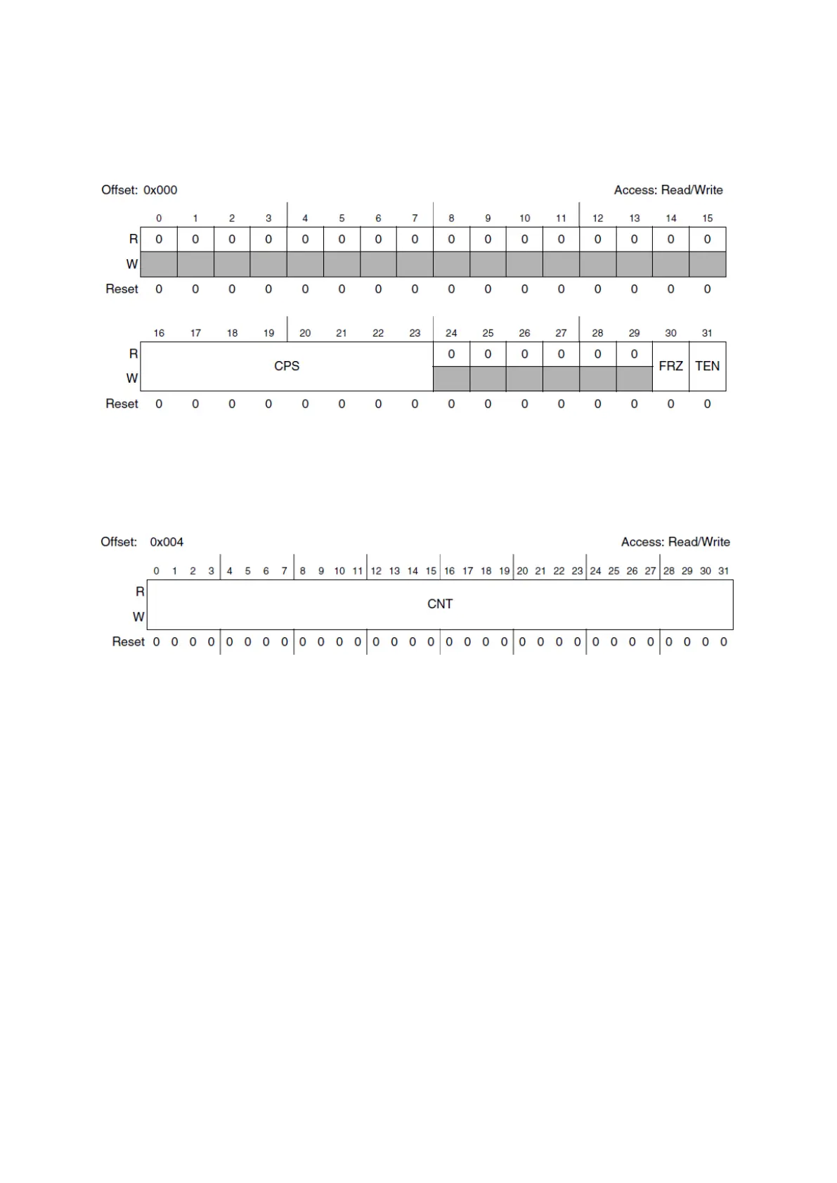
Figure 35 : STM Control Register (R.M. Rev8 – Fig. 24-2)
The control register (STM_CR) can enable the clock using TEN (Timer Enable, write ‘1’ to
enable) and it can set the timers behaviour in debug with FRZ (Freeze, write ‘1’ to stop the timer
in debug mode). The field CPS is the counter prescaler, the clock is divided by (CPS[7:0]+1).
Figure 36 : STM Count Register (R.M. Rev8 – Fig. 24-3)
The value of the counter is stored in the count register (STM_CNT). The counter goes up to
0xFFFFFFFF and then starts again from 0x00000000.
Each of the four channels [0...3] have the following registers:
STM Channel Control Register (STM_CCR[n]) with a one bit enable field, CEN.
STM Channel Interrupt Register (STM_CIR[n]) with a one bit channel interrupt flag field
CIF (write ’1’ to clear the flag)
STM Channel Compare Register (STM_CMP[n]) with a 32-bit field compare value CMP.
An interrupt is generated when the counter value reaches the channel compare value (interrupt
n° 30-33).
PIT: Periodic Interrupt Timer
There are six independent 32-bit count-down timers in this module, with no prescaler, each
having independent timeout values and interrupts. The module has one general control register
and each timer has four configuration registers.