An EVTCFGR[n] register has the following fields:
A trigger masking bit (TM), set this bit to enable triggers.
A clear flag (CLR_FLAG) bit to force the software to send and Flag_Ack signal to the
timers. If this bit is set, the Flag_Ack is sent continuously ( may cause a loss of event), and
when it is clear Flag_Ack is handled automatically.
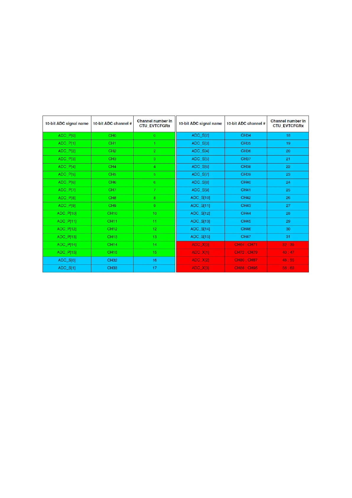
A channel value field (CHANNEL_VALUE) to specify the ADC channel to be converted.
(See the table below for channels associations with these values).
Figure 78 : ADC assignment to CTU register (R.M. Rev8 – Table 26-4)
3.
The CTU enable bit has to be set to enable CTU triggered conversions. If a CTU conversion is
triggered while a normal conversion is ongoing, it is treated just like an injected conversion. The
normal conversion is aborted, and it resumes once the CTU conversion is completed.
However, if a CTU conversion is triggered, during and ongoing injected conversion, the injected
conversion is aborted and does not resume later. This situation is signalled by the ADC’s status
register’s JABORT bit.
Implementing a feedback loop with ADC-CTU-eMIOS
This example can be used for implementing the feedback loop of a control system; at each PWM
period an input can be read, and PWM’s duty cycle can be altered depending on it. It is very
similar to the chapter 6’s section 3. But in this one the PIT is removed, and ADC interrupt
changes both PWM duty cycle and the LEDs (works on flag EOCTU), there is no internal state.