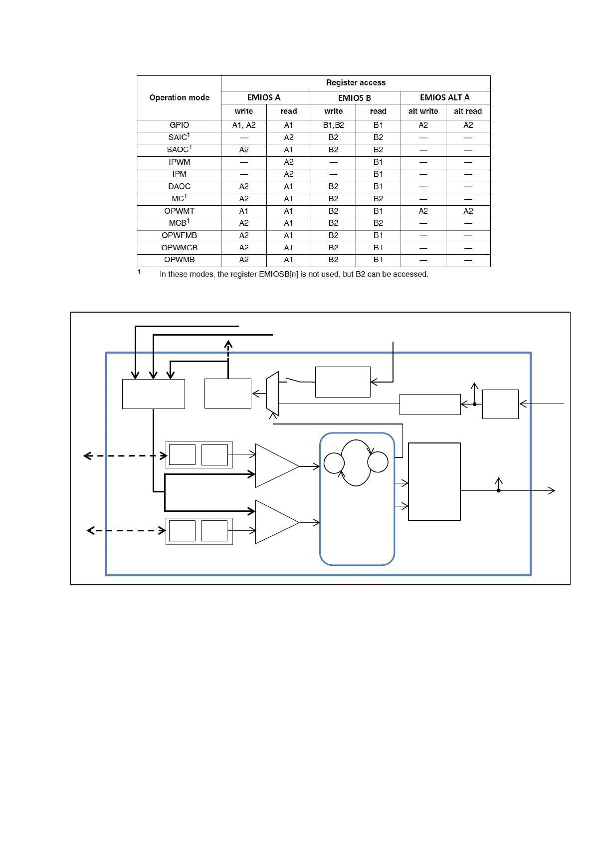
Figure 47 : eMIOS A, B and Alt A Register R/W (R.M. Rev8 – Table 24-16)
Figure 48 : An eMIOS Channel’s Block Diagram
In the following sections, we will study different modes of operations and how registers A and
B behave in each one of them.
GPIO: General Purpose Input/Output
In General Purpose Input/Output mode all input capture, output compare and timing functions
are disabled. Registers A and B hold the same value. All channels are in this mode by default and
have to go through this mode when a mode change occurs.
eMIOS Internal
Counter Clock
Secondary Counter Bus
(B,C…)