Edge Selection (EDSEL) bit: for input modes, this bit selects whether both edges are
triggering (‘1’) or a single edge defined by EDPOL (‘0’). For GPIO input mode, it selects if a
flag can be generated (‘1’: no flag is generated, ‘0’: it’s generated as defined by EDPOL). And
for SAOC mode, it selects if output flip-flop is toggled at each match (see the section below).
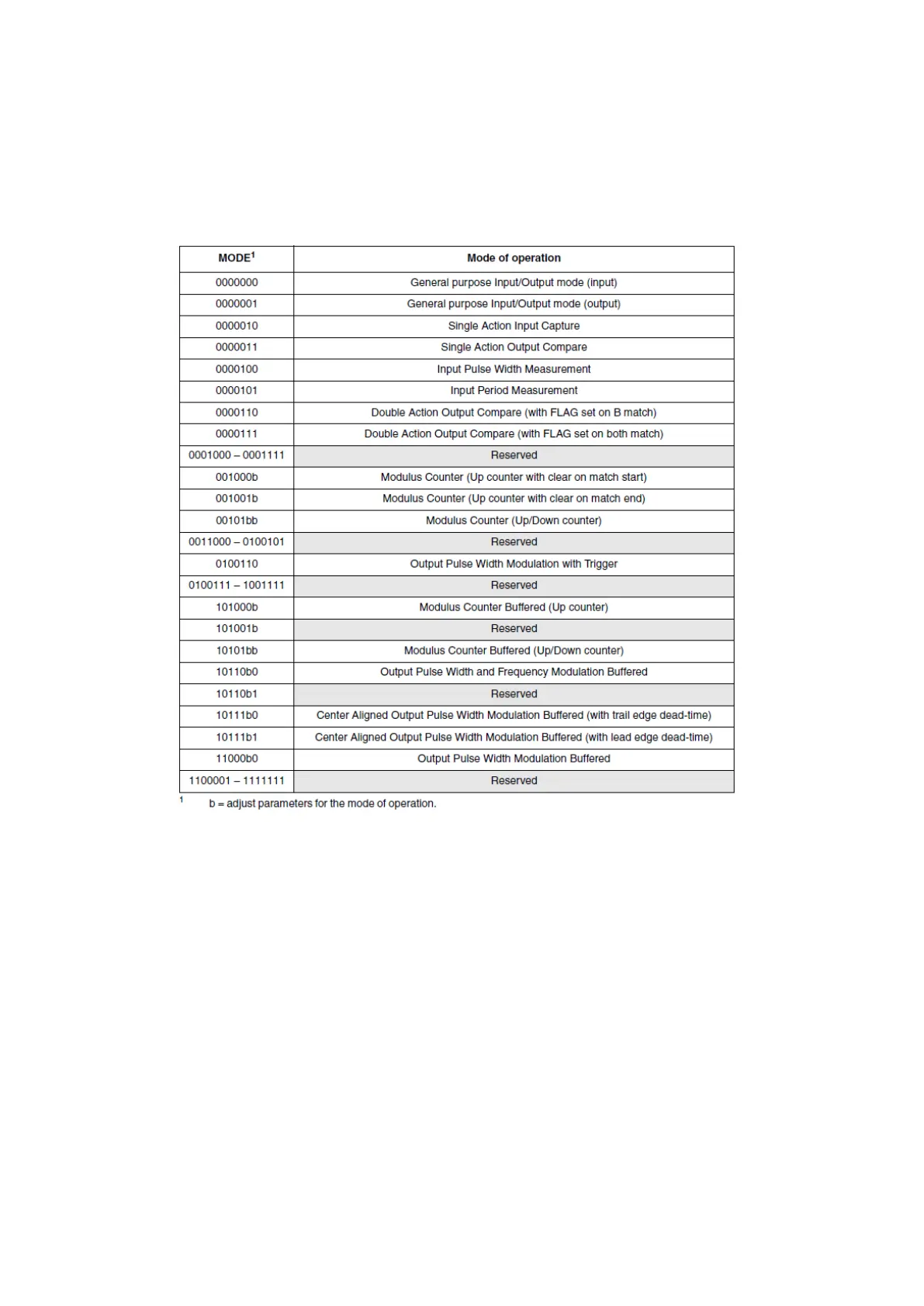
MODE field is used for mode selection as described in the table below.
Figure 46 : Channel Mode Selection (R.M. Rev8 – Table 24-21)
Another major register for a channel is the status register (EMIOS_CH[n]_CSR) containing the
flag bit (FLAG, write ‘1’ to clear), overrun bit (OVR: write ‘1’ to clear) which is set when a flag
generation occurs while FLAG was already set. Overflow bit (OVFL: write ‘1’ to clear) is set when
an overflow has occurred in the internal counter. Two read only fields allow getting the input
(UCIN) or output (UCOUT) state of the pin.
A 16-bit counter register (EMIOS_CH[n]_CCNTR) that contains the current value of the channel’s
internal counter.
And finally, there are three 16-bit data registers that will set the behaviour of the channel in a
particular mode of operation. eMIOS Unified Channel A register (EMIOS_CH[n]_CADR), eMIOS UC
B register (EMIOS_CH[n]_CBDR) and eMIOS Alternate A register (EMIOS_CH[n]_ALTCADR).
These three registers are used to read or write the four internal registers (A1; A2; B1; B2)
previously mentioned. The following table shows the value assignment of different modes.