IPWM: Input Pulse Width Measurement
The Input Pulse Width Measurement mode (MODE[0:6]=0000100), is the measurement of the
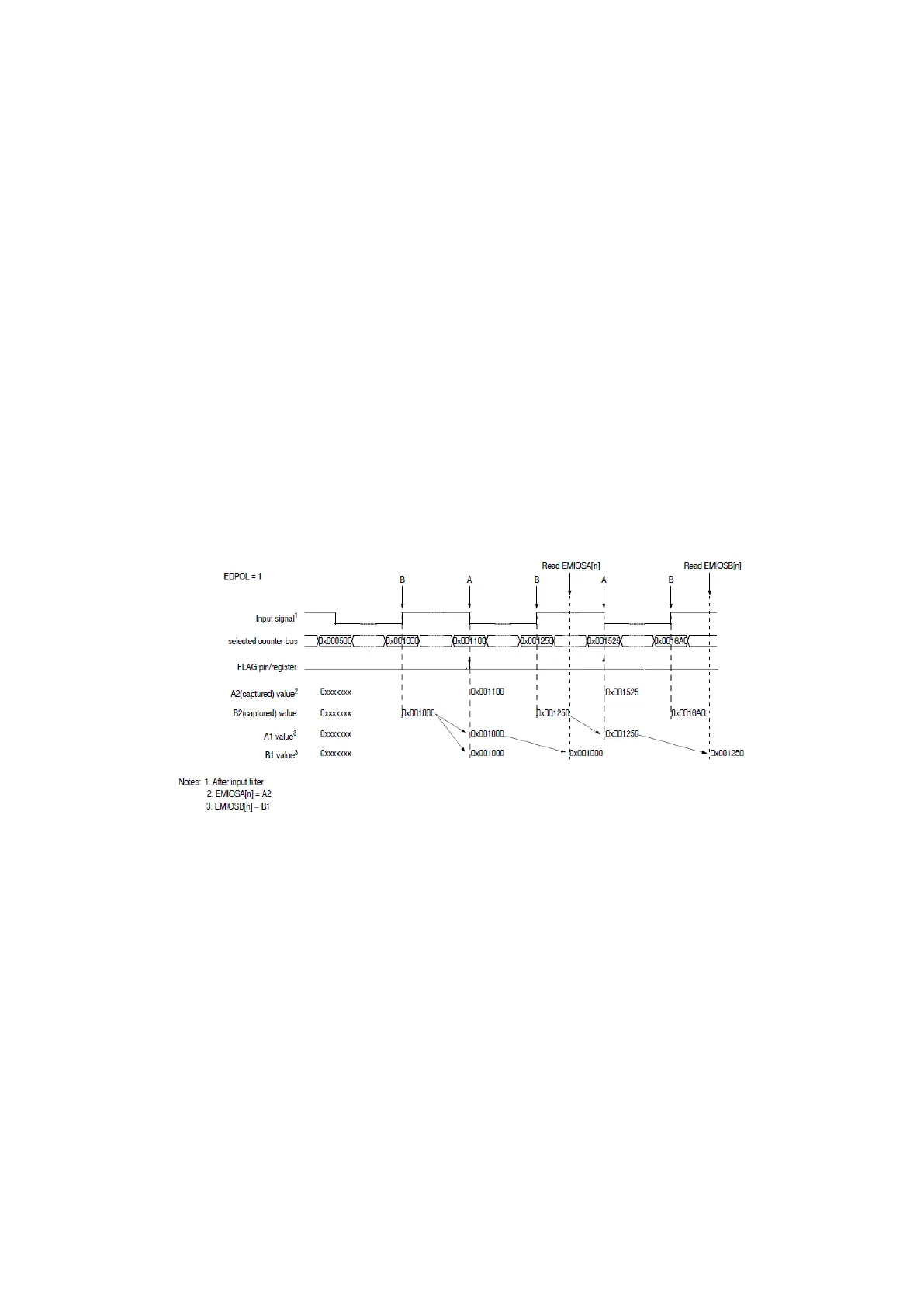
width of a positive or a negative (depending on EDPOL) pulse by capturing the leading edge on
B1 and the trailing edge on A2.
The capture on A2 is disabled until B2 gets its first leading edge, then the selected counter bus
(BSL) count value is stored on B2. When the trailing edge is detected, the count value is stored in
A2, the flag bit is set and the value of register B2 is transferred to registers B1 and A1. If new
capture events occur while the flag bit is set, then the flag bit will remain but registers will be
updated with new data.
In order to get coherent width measurement, a read on the register A (so A2) will disable
transfers from B2 to B1 and force a transfer from A1 to B1. The value in B1 will be intact for the
upcoming read on the register B. By subtracting B1 from A2, we can get the pulse width. (See
figure below for an illustration of these register transfers).
Therefore, once a flag is set, reading the register A, then reading the register B and subtracting
them, will always give a coherent reading.
Figure 51 : IPWM Example (R.M. Rev8 – Fig. 24-23)
NOTE: If a pulse measurement happens during a counter roll over, maximum counter value has
to be added to A2 before subtracting B2.
IPM: Input Period Measurement
The Input Period Measurement mode (MODE[0:6]=0000101), is the measurement of the period
of an input signal by capturing two consecutive rising edges or two consecutive falling edges
(depending on EDPOL). The principle is very similar to the IPWM’s way of operating (see the
previous section).
When the first edge of selected polarity is detected, the count value is stored in A2 and B2 and
the previous value of B2 is transferred to B1 and A1. On the following edges, the flag bit is set
and the value of register B2 is transferred to B1 and A1 and the new count value is captured.