And finally, there is an interrupt flag register (WTISR) for all watchdogs, containing six flags,
WDGxL and WDGxH, x=0…3, for each interrupt. And a mask register (WTIMR) with six match
bits, MSKWDGxL and MSKWDGxH, x=0…3, that has to be set to enable the corresponding
interrupts.
There are mask registers for enabling sampling phase for each channel; for normal conversions
we have NCMR[0…2] and for injected conversion we have JCMR[0…2]. Both registers have one-
bit fields for each registers (16 in types 0 and 1 registers, 32 in type 2 register) named CHx,
x=0..31. The sampling of a channel can be enabled by setting these fields.
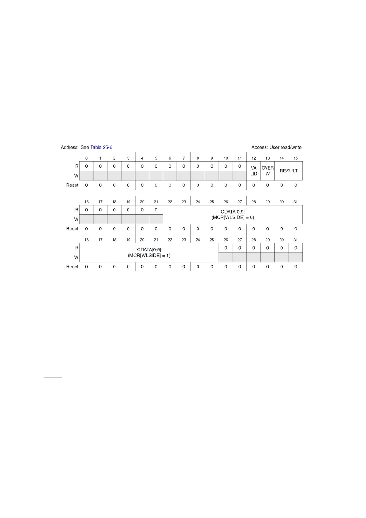
Figure 74 : Channel Data Register (R.M. Rev8 – Fig. 25-35)
There are 96 Channel Data Registers (CDR[0…95]) where channels 0…15 are for precision
channels, 32…47 for standard channels and 64…95 are for external multiplexed channels. These
registers contain information about the converted result. The field VALID notifies if a new value
has been written (and it is automatically cleared when data is read). OVERW signals if a previous
non read data has been overwritten (can only occur if OWREN is set) and RESULT indicates from
which mode of conversion the data comes (00:Normal, 01:Injected, 10:CTU). CDATA field
contains the converted data, and its position on the register depends on WLSIDE bit on MCR
register.
NOTE: the C header file only supports WLSIDE=0 field!!
ADC Example with PIT and eMIOS
In this example, an ADC reads a potentiometers value and PIT2 triggers an injected conversion
periodically using the hardware connection PIT2 has with ADC. Once a conversion ends,
depending on user’s selection, the value read is either displayed on four LEDs or it is used to set
an eMIOS OPWMs duty cycle.
For setting up the timer the following functions are used: