On external interrupts, DSPI is not mentioned because it is thought to be used in master mode
but it can still be done (see pad configurations) if needed. A more appropriate use would be, for
instance, to wake up the device using CAN signals.
The 18 external sources of the Wakeup Unit will trigger a wakeup signal in STANDBY/STOP
modes but they can still be used as extra external interrupts during a RUN mode. These Wakeup
pins are enabled in all modes, so, in order to ensure that their current consumption stays
minimal, internal pull-up resistors (see following registers) should be used with unused pins.
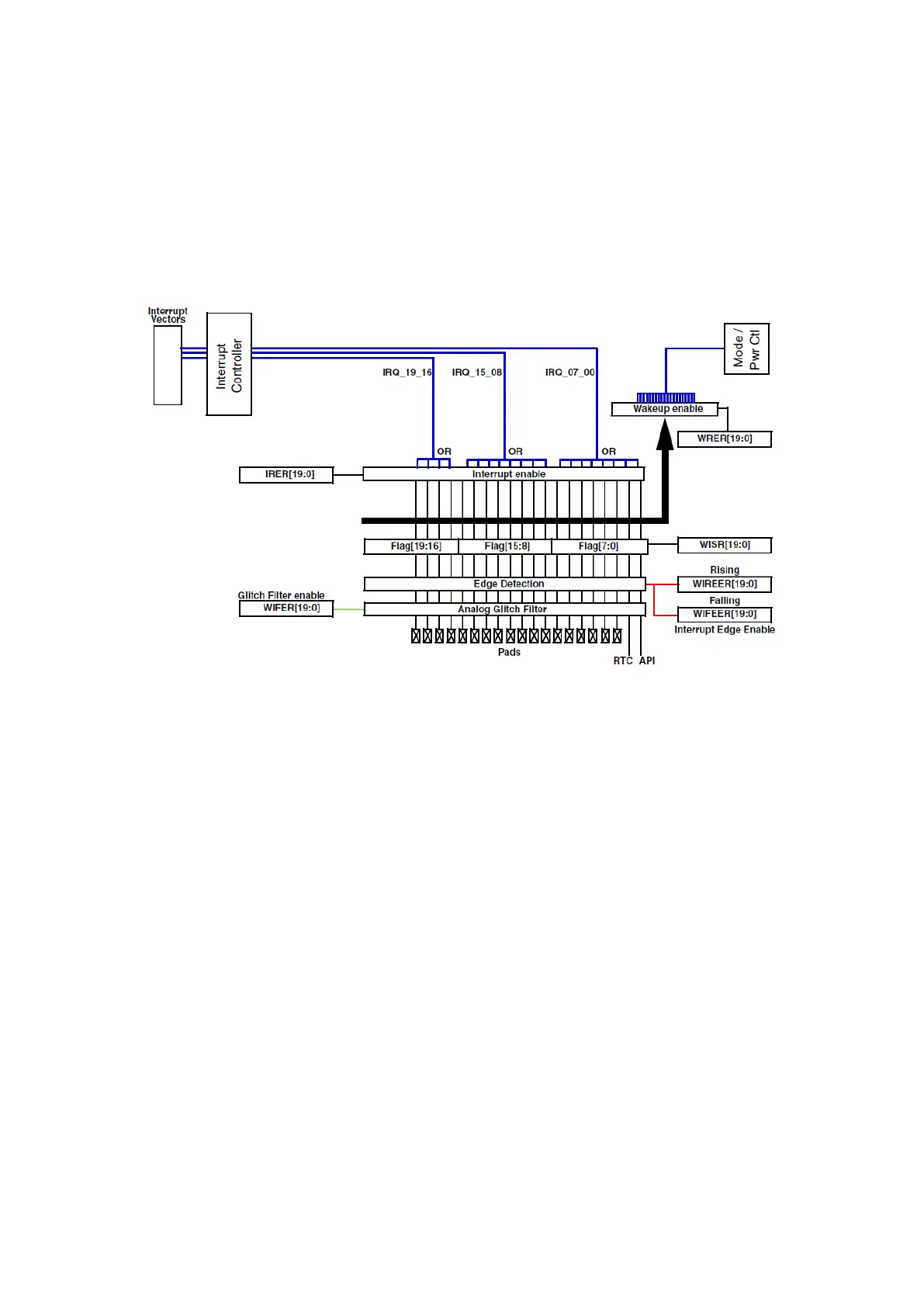
Figure 83 : Wakeup unit external interrupt pad diagram (R.M. Rev8 – Fig. 12-12)
The non maskable interrupt (NMI) functionalities of this unit will not be explained here.
Configuration of wakeup events
This unit has a few registers for configuring and managing wakeup events, all of them have a 20-
bit modifiable field with each bit being associated to a wakeup source.
The Wakeup/Interrupt Filter Enable Register (WIFER) is used to enable a non-configurable
filter on the input signals. Its field is called IFE[19:0]. All filters are disabled by default.
Similarly the Wakeup/Interrupt Pullup Enable Register (WIPUER), with its IPUE[19:0] field can
enable a pull-up register on the selected interrupt pads. It should be used on unused pins to
reduce current leakage.
Then, Wakeup/Interrupt Rising/Falling-Edge Event Enable Registers (WIREER/WIFEER) with
IREE/IFEE fields can be used to select a signal edge (or both) as a triggering event.
The Interrupt/Wakeup Request Enable Registers (IRER/WRER) are used to enable the
generation of an interrupt/wakeup request from the triggering event.
And Wakeup/Interrupt Status Flag Register (WISR) contains the flag generated by the triggering
event and can be cleared by writing ‘1’.