Some peripherals’ inputs can be received from multiple pads, in this case using PSMI registers’
PADSEL fields; one of the possible pads must be selected. See Appendix 3 for more information
about possible selections. It is mostly needed by communication modules.
Here’s an example code that sets pads connected to four LEDs as GPIO outputs and switch S1 as
an input.
GPIO: General Purpose Input/Output
General purpose input/output (GPIO) functionality allows reading and writing binary values on
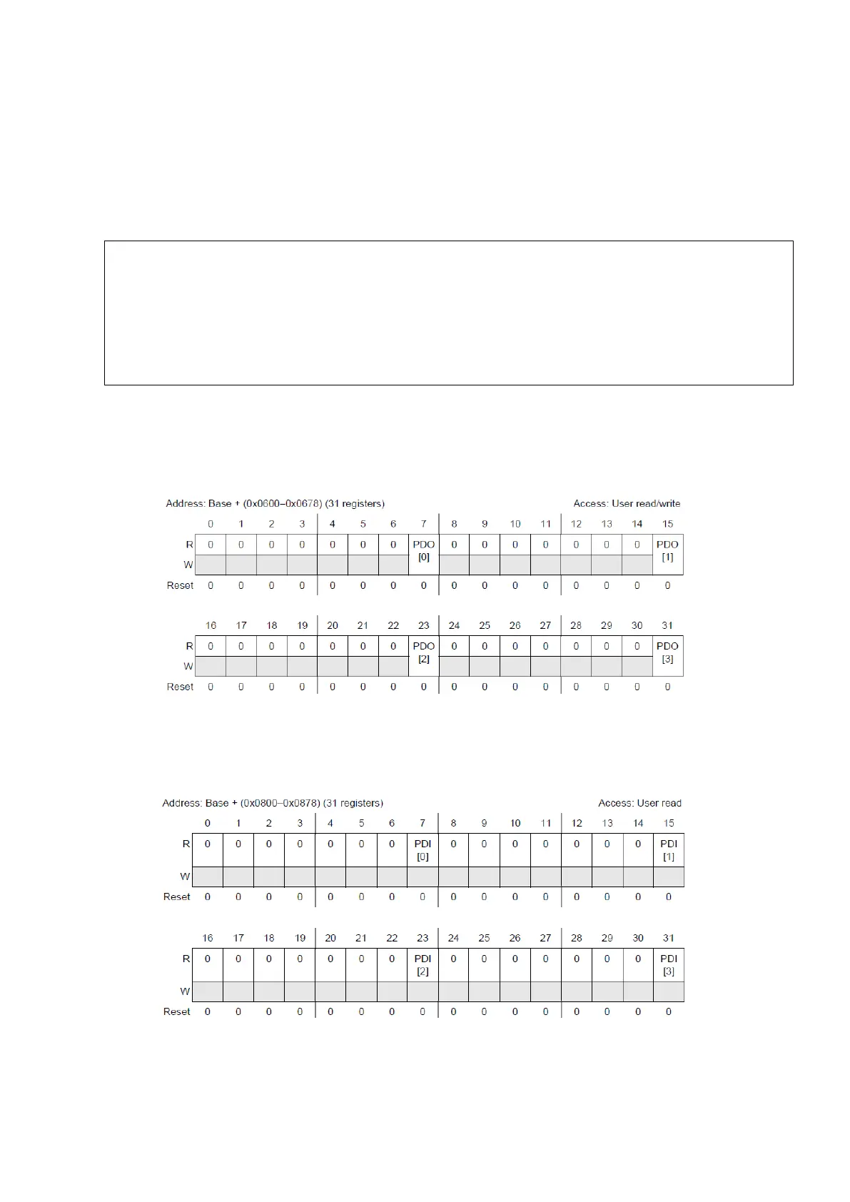
pins (0V/5V). To set or clear a pad we need to use GPIO Pad Data Output register.
Figure 24 : GPIO Pad Data Output Register (Reference Manual Rev7 – Fig. 8-12)
These 31 32-bit registers can be seen as 123 8-bit registers with only one field to set or clear the
pad. A very similar register for reading inputs exists is show on the figure below.
Figure 25 : GPIO Pad Data Input Register (Reference Manual Rev7 – Fig. 8-13)
{
SIU.PCR[68].R = 0x0200; /* LEDs are connected between PORT E pins and 5V */
SIU.PCR[69].R = 0x0200; /* PE 4 to PE 7 */
SIU.PCR[70].R = 0x0200;
SIU.PCR[71].R = 0x0200;
SIU.PCR[64].R = 0x0100; /* PE 0 */