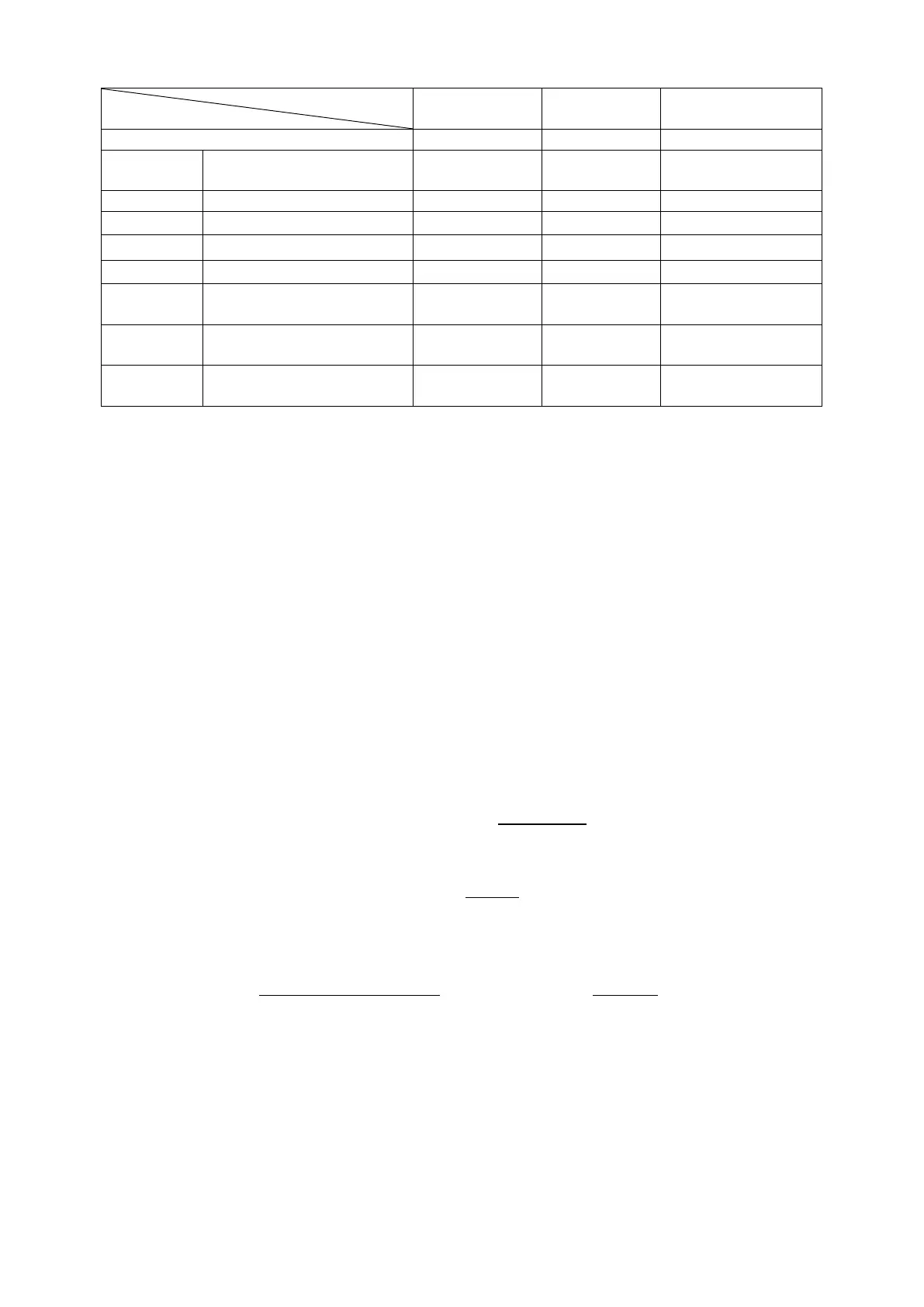
Minimum time between
start signal and clock start
Min. time between clock
release and stop signal
Max. time for valid SDA
after SCL falling edge
0.6V/6mA situation in fast-mode is the worst case situation where
= 400
and
= 400.
Devices and the cable sizes create parasitic capacitances that add up to be the bus capacitance
. For an accurate value, this has to be measured someway, but if it is not possible, a good
way of estimating it is
=
+
, where
is 20pF for each device pad (10pF
for pad load+10pF for connections) and
is estimated on cable by assuming 50-100pF/m
on cables.
Pull-up resistor calculation
Pull-up resistance value is limited by low level current consumption of the devices and the RC
time constant of the bus cause by the bus capacitance.
The bus capacitance limitation can be calculated using RC charging formula. In I²C specifications,
input Low and High values are defined respectively as 30% and 70% of the supply Vdd. By
solving
(
)
=
1
/
for at 0.3 at 0.7 values, we get
= 0.356675 × and
= 1.203970 × , and then
= 0.847298 × .
So the maximum pull-up resistance value is:
=
.×
.
The minimum value is limited by the current consumption of the device, using ohm’s law when
the output of a device is at low, we have
=
.
Example at 100pF and with a baud rate of 400kHz:
=
300 × 10
0.847298 × 100 × 10
= 3541 ;
=
5 0.4
3 × 10
= 1533
Therefore a pull-up resistor of 2.2k is a good choice at this specifications.
Using the I²C module
2.1.
There is only one I²C module in MPC5604B and it features pretty much every I²C features except
for general call address and 10-bit addressing. These modules pins and signals are compatible