CAN protocol uses variable length frames (depending on data size or standard/extended ID) as
.
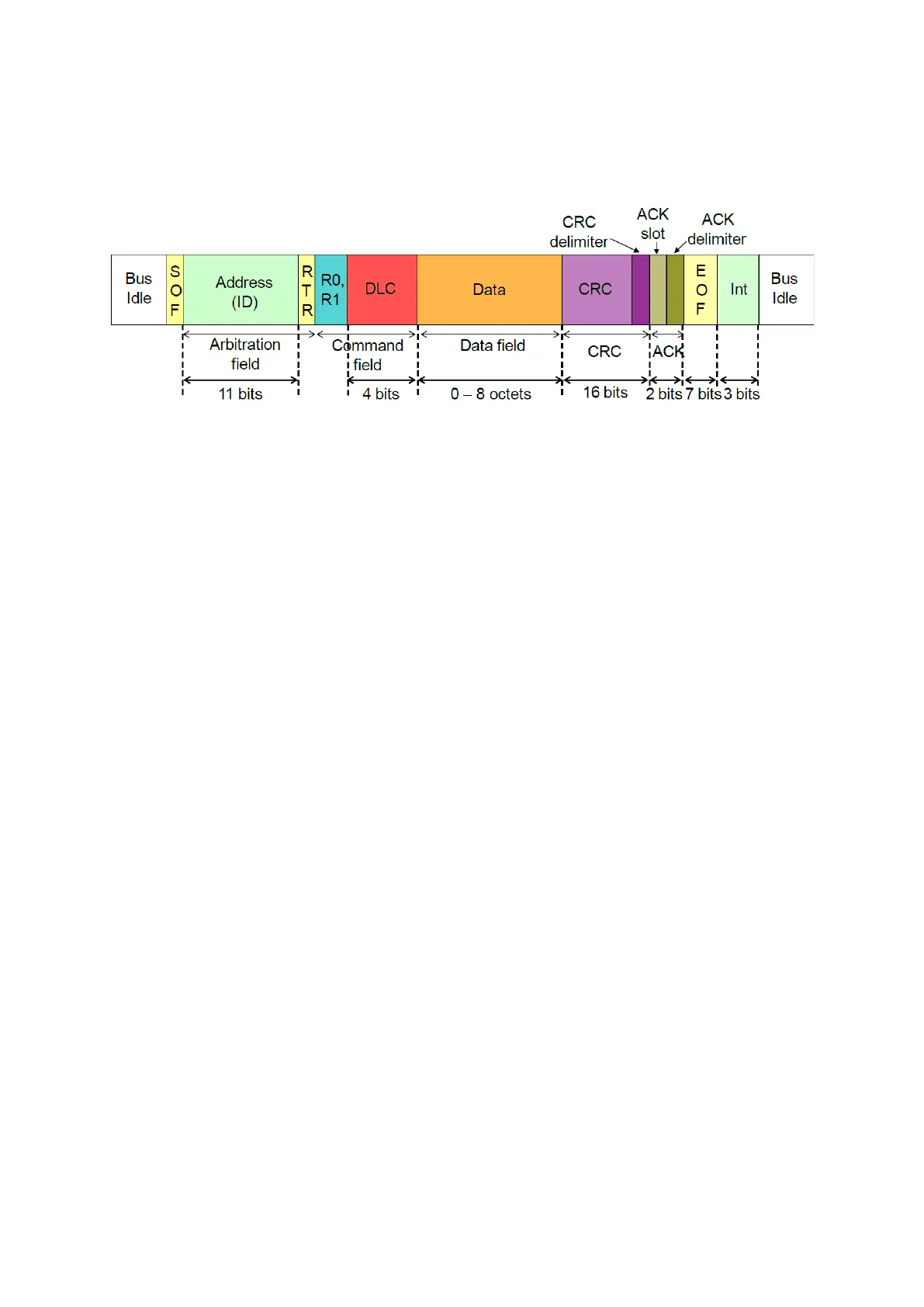
Figure 112 : CAN 2.0A standard frame format
The figure above shows different fields included in a frame. Here’s brief descriptions of some
fields:
SOF(Start of Frame): a dominant bit set by the transmitter. Other devices will not try to
transmit from now on.
Arbitration field: in standard 2.0A, this 12-bit field is made of a 11-bit ID and a RTR
(Remote Transmission Request) bit. ID is a way of identifying a context for the message
but it also sets the messages priority; priority is higher for lower IDs. RTR allows a
device to request data transmission from another by sending a frame with no data when
it is recessive. In standard 2.0B, this field is extended to 32-bit with a new id field of 18-
bits (so making a total ID of 29-bits) and with two recessive flag bits.
Command field: has two reserved bits (for future standards, one of them is used in CAN
2.0B to specify an extended ID or not) at dominant state and a 4-bit DLC (Data Length
Code) field which indicates the number of bytes contained within the frame (limited to
8).
Data field: is made of up to 8 bytes of data, depending on DLC’s value. MSB is transferred
first in each byte.
CRC (Cyclic Redundancy Code) field is a 15-bit error checking code followed by a
recessive delimiter bit.
ACK (Acknowledge) field has one ACK slot where transmitter sends recessive and
receiver has to send dominant to acknowledge. This bit is followed by another recessive
delimiter bit.
EOF (End of Frame) is made of 7 successive recessive bits.
INT(Interframe) is the separator between two successive frames, made of at least three
recessive bits.
There are also
that are made of 6-12 dominant bits which is superposition of
different devices error flags. These flags are followed by 8 recessive delimiter bits. Six
dominant bits point to an active error flag and six recessive bits is emitted on a passive error
flag.