is DAOC with a flag generation on the B match and MODE[0:6]=0000111 is DAOC with a flag
generated on both matches.
For further pulse generation, the comparators have to be re-enabled by transfer of data written
to A2/B2 to A1/B1.
The Modulus Counter mode (MODE[0:6]=0010bbb) is used to generate a counter that can be a
time base for a counter bus or a general purpose timer. In this mode an internal counter counts
up, following a reference clock until a match occurs. And then it is either cleared, or it changes
count direction. There are three bits on the mode field that can configure the operating process:
MODE[6] selects the reference clock, if this bit is set, then the clock is an external clock
connected to the pin as an input and the ticking edge is determined by EDPOL and
EDSEL, if it is clear then the internal prescaled clock source is used.
MODE[5] defines whether the internal counter is cleared on match start or on an match
end. When this bit is clear, the counter is cleared and the flag is set as soon as the match
occurs (which can lead to a shorter 0 count) and when it is set, the counter is cleared and
the flag is set on the next tick following the match.
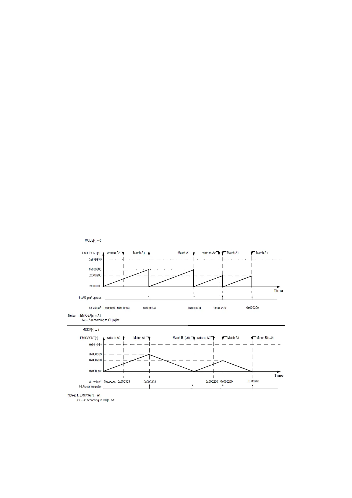
MODE[4] selects between two counting modes. When it is cleared, the counter counts
up to match A1 value and then it is cleared, and when it is set, after the match with A1,
the counter counts down till it matches with B1 and changes direction again and so on.
Figure 54 : Modulus Counter Up and Up/Down Mode Examples (R.M. Rev8 – Fig. 24-30/31)
Only values greater than 0x0 should be written on the register A and register B1 is always
cleared in this mode and cannot be changed. If A is changed during operation, the behavior of the
counter depends on its actual state; if the counter is less than the new value of A, there won’t be