A timer configuration example has been built using STM, PIT and RTC/API where each module
has to toggle a LED at 5Hz frequency (therefore generating à 2.5Hz square wave). Their
precision and ease of use will be compared.
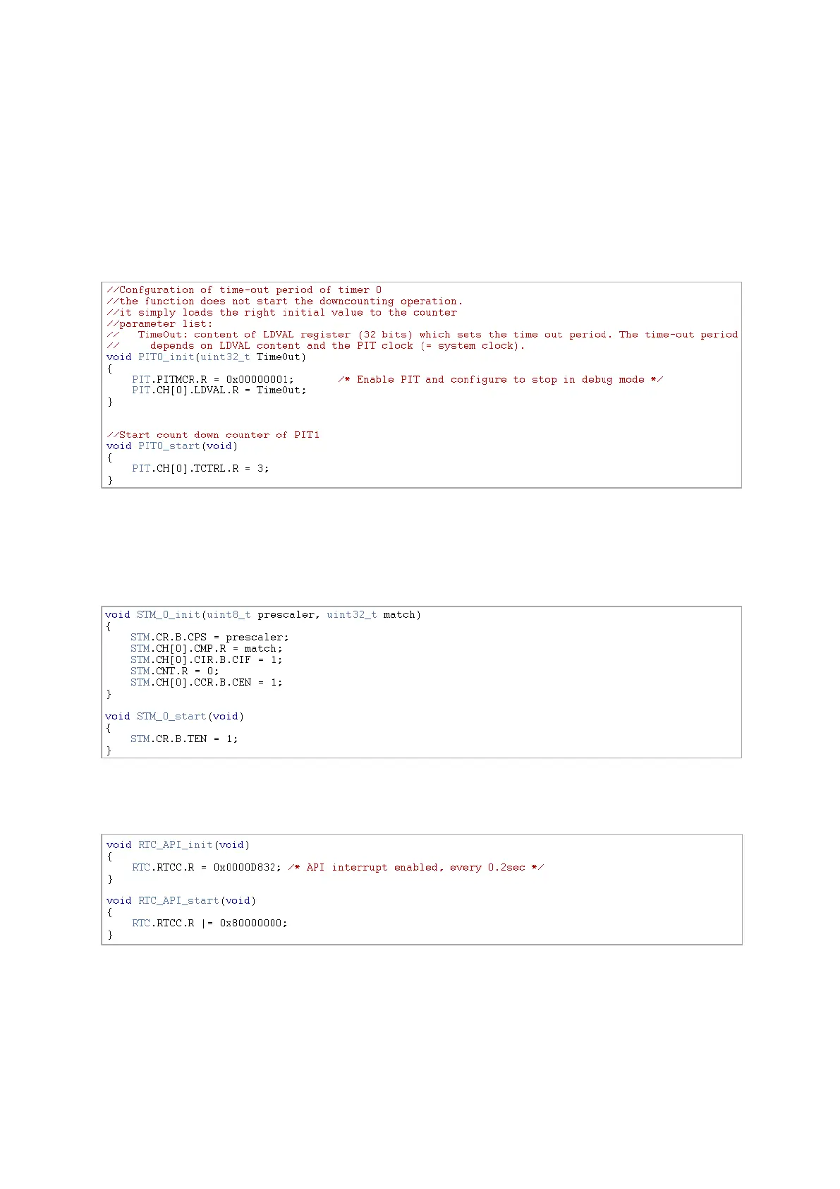
Let’s start with PIT; it has to be initialized with a TimeOut value which will set the frequency. If
we chose the use 8MHz crystal clock, it has to be 1600000=0x186A00 to raise an interrupt at
5Hz frequency. The start function will enable the counter and the interrupt.
For STM it will be harder to generate periodic interrupts, as the counter will try to roll-over after
a match. The 8-bit prescaler field is not large enough to make a 5Hz roll-over therefore after
each match interrupt; the counter has to be reset. This will deteriorate the resulting frequency a
bit.
For configuring RTC/API, we enable API interrupts and using the resolution table we chose SIRC
with the 512 divider. This allows getting an interrupt raised at a 5Hz frequency.
Interrupt handlers of each timer is similar: clear the flag, toggle the LED, but STM’s interrupt
also contains an instruction to clear the counter.
In the end, by measuring the square wawe’s frequency we got 2.5Hz with the PIT, 2.499Hz with
the STM. With the RTC clock we got different values between 1.9Hz and 2.8Hz and we could set
it to 2.5Hz by trimming the SIRC clock with a trimming value of 4.