58
CTU: Cross Triggering Unit
1.
The Cross Triggering Unit synchronises an ADC conversion with a timer (a PIT or eMIOS)
without needing to generate an interrupt. A conversion is only delayed by a cycle from the
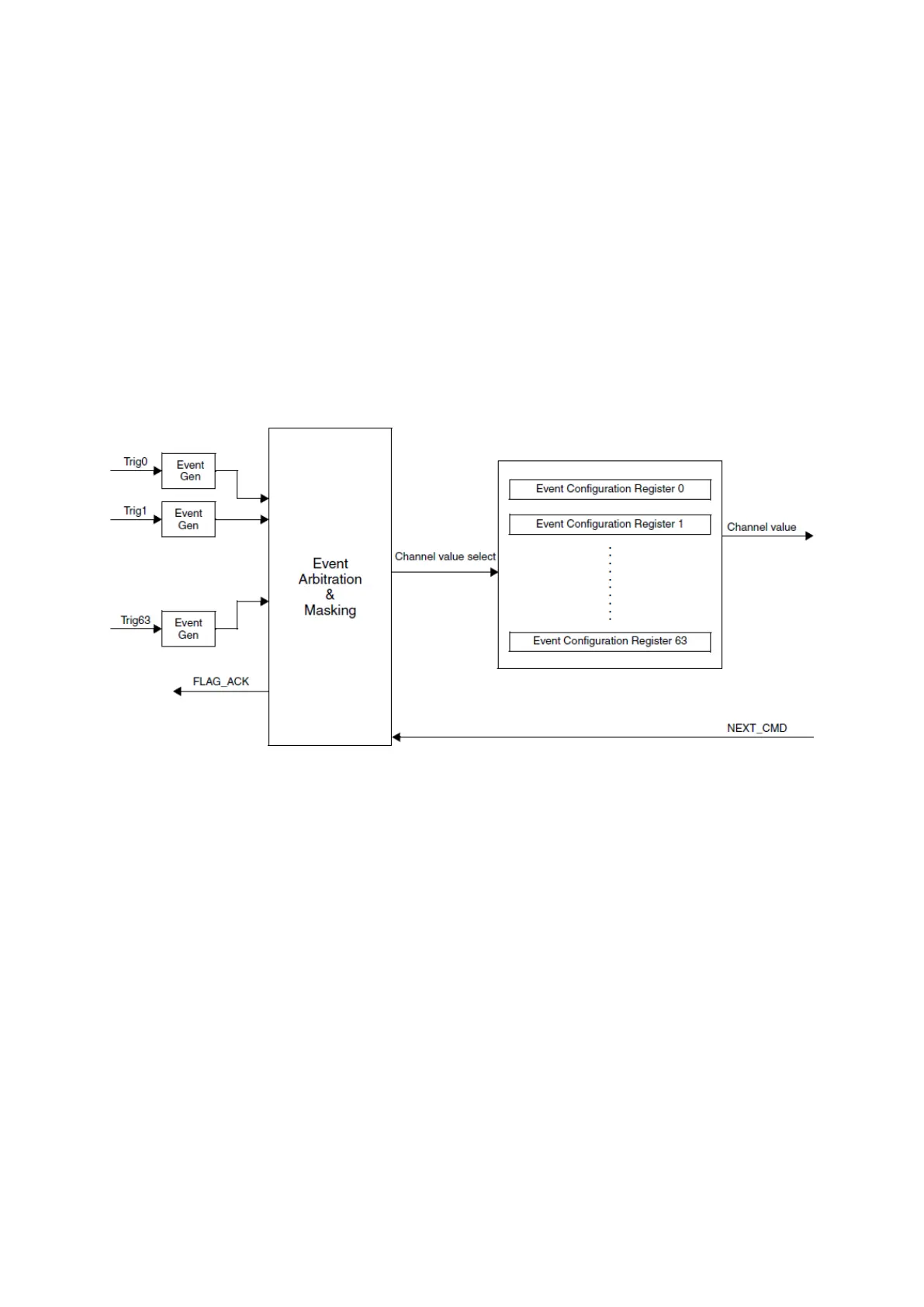
trigger event of the timer. The following block diagram illustrates the CTU module.
Figure 75 : CTU Block Diagram (R.M. Rev8 – Fig. 26-1)
There are 64 possible trigger sources (in practice, it is fewer, see table below) and each one of
them has an Event Configuration Register which makes a connection between the trigger source
and an ADC channel to be converted. A FLAG_ACK signal is sent to the event source, if the source
is a PIT, for eMIOS, the flags are cleared automatically.
This module can start an ADC faster than an IRQ, with negligible delay between the trigger event
and the start of the ADC conversion. Therefore, this module is useful for applications like system
identification, instrumentation, regulation with precise timing.
Example: using an OPWMT to generate and output signal into a system and then instantly make
ADC measurement on the output of this system. In function of the conversion result, the PWM
duty cycle can be readapted for the control cycle.