Here is the list of data fields relevant to the UART in the LIN control register 1 (LINCR1):
AWUM: Automatic Wake-Up Mode, when set, on activity on Rx or in internal transmit
registers, the module goes automatically to the Normal mode, clearing SLEEP bit.
SFTM: Self-Test Mode, set this bit to enable this mode.
LBKM: Loop Back Mode, set this bit to enable this mode.
RBLM: Receive Buffer Locked Mode, when this bit is set, if the receive buffer is full, next
incoming data are discarded. Otherwise incoming data overwrites the previous one.
SLEEP: Sleep Mode Request
INIT: Initialisation Request
With the exception of SLEEP and INIT, all these fields can only be changed in Initialisation mode.
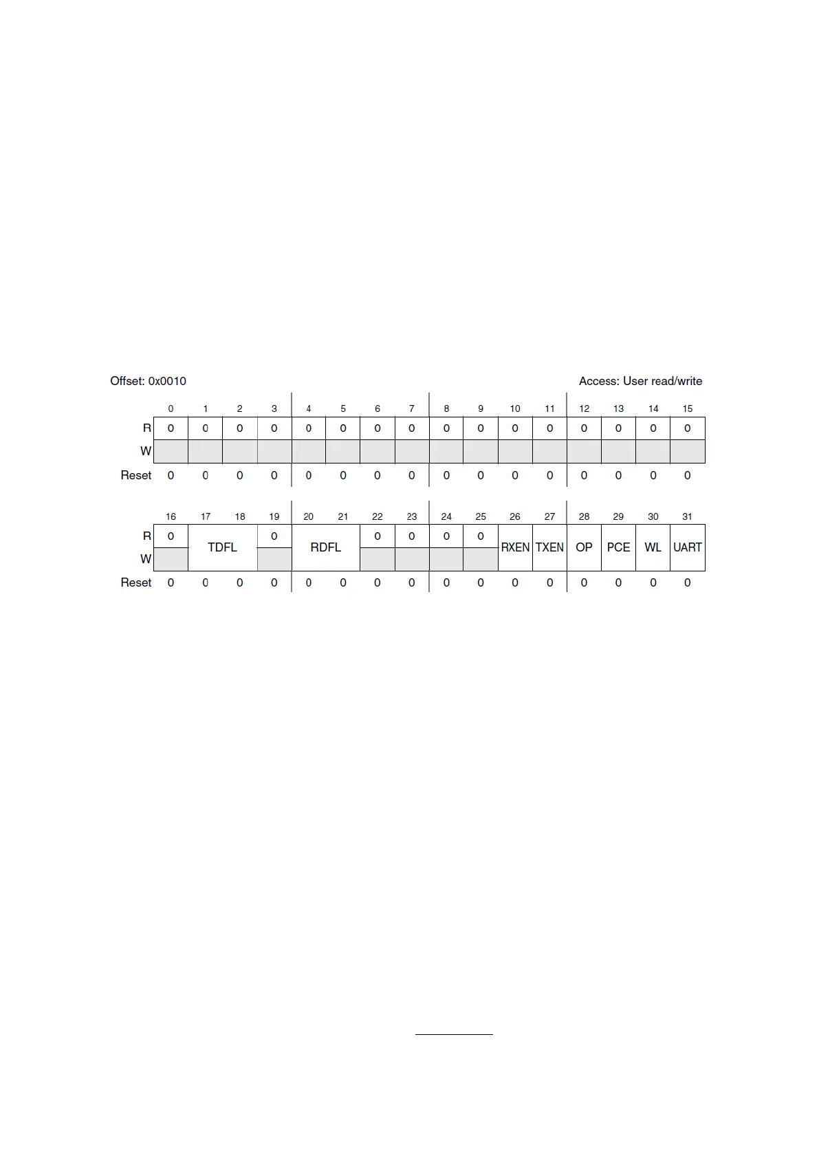
Figure 100 : UART Mode Control Register (R.M. Rev8 –Fig. 21-10)
The UART mode Control Register (UARTCR) allows configuring different parameters related to
this protocol. Different fields of this register are:
UART: UART mode enable, set this bit to be able to modify other fields of this register.
WL : Word Length in UART mode; 7 bit data + parity bit (0) or 8 bit data + parity bit (1).
(Parity bit is optional). Only set in Initialisation mode.
PCE: Parity Control Enable, if set, a parity bit is attached to the message and a parity
check is enabled on received data. Only set in Initialisation mode.
OP: Odd Parity, if set, the sent parity is odd, otherwise even. Only set in Initialisation
mode.
TXEN: Transmitter Enable. Transmission starts when this bit is set and data is written to
the transmit buffer.
RXEN: Receiver Enable.
RDFL: Receiver Data Field Length, Receive buffer size = RDFL[0:1]+1 bytes.
TDFL: Transmitter Data Field Length, Transmit buffer size = TDFL[0:1]+1 bytes.
The baud rate of this module is set by an unsigned fixed point number called LFDIV.
Tx/Rx
=
_
16 ×