Figure 27 : Masked Parallel GPIO Pad Data Out Registers (Reference Manual Rev7 – Table 8-18)
Here’s the equivalent code for turning all LEDs off for the previous code written with these new
registers:
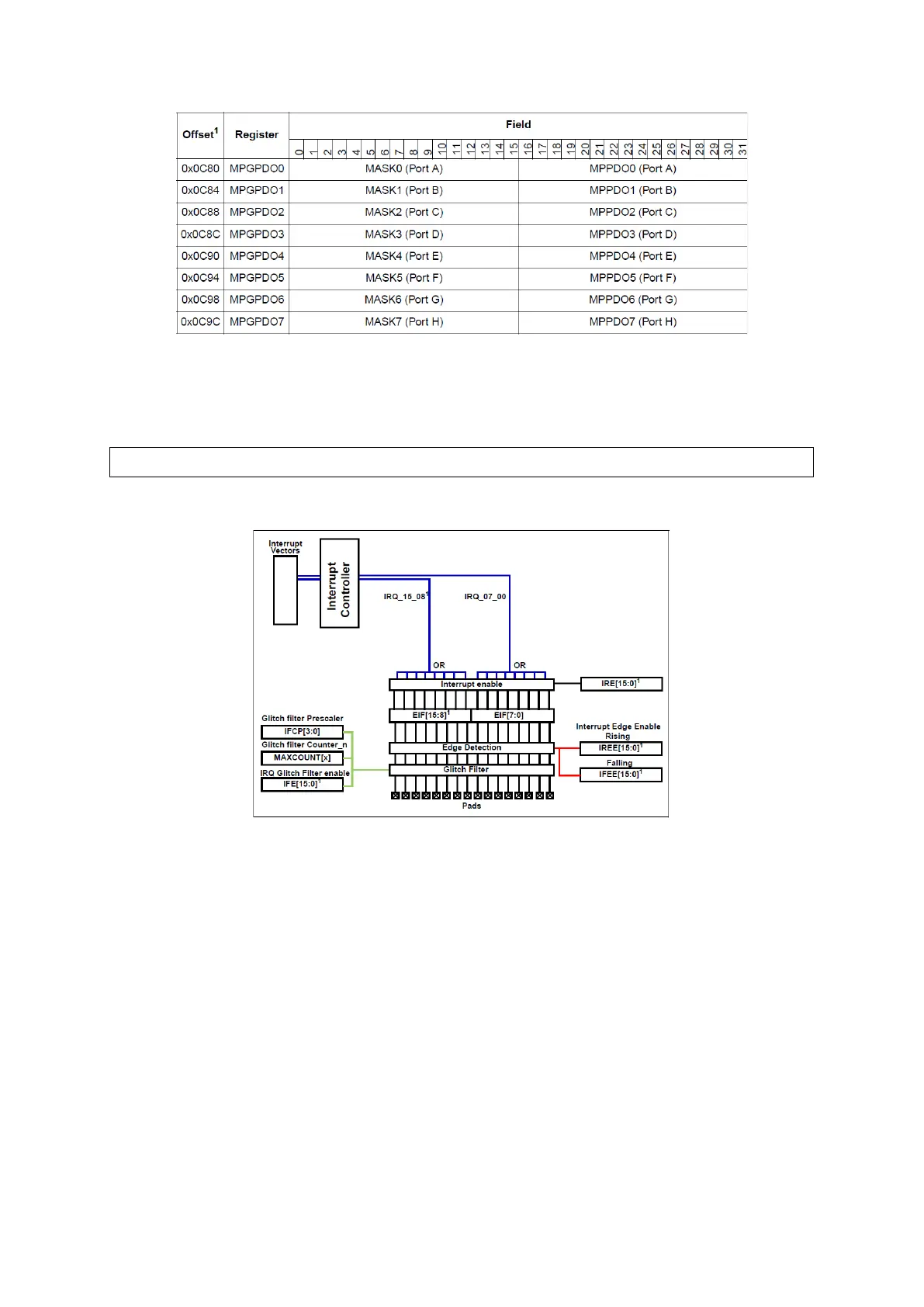
Figure 28 : External Interrupt Pad Diagram (Reference Manual Rev7 – Fig. 8-17)
16 pads among 123 have External Interrupt functionality, a rising or falling edge can be set to
trigger an interrupt. There are two system interrupt vectors spared for EIRQ pins, IRQ0 for
EIRQ[0:7] and IRQ2 for EIRQ[8:15]. Looking at the diagram above we can identify following
registers:
Interrupt Request Enable Register (IRER) with a 16-bit field to specify pads that can
request interrupts,
Interrupt Status Flag Register (ISR): has a 16-bit flag field called EIF, flags can be
cleared by writing 1,
Interrupt Rising-Edge Event Enable Register (IREER): a rising edge triggers the
interrupt,
Interrupt Falling-Edge Event Enable Register (IFEER): a falling edge triggers the
interrupt, (note that a pad can trigger interrupts on both rising and falling edge
events).
SIU.MPGPDO[4].R = 0x0F000F00; // All LEDs are off.