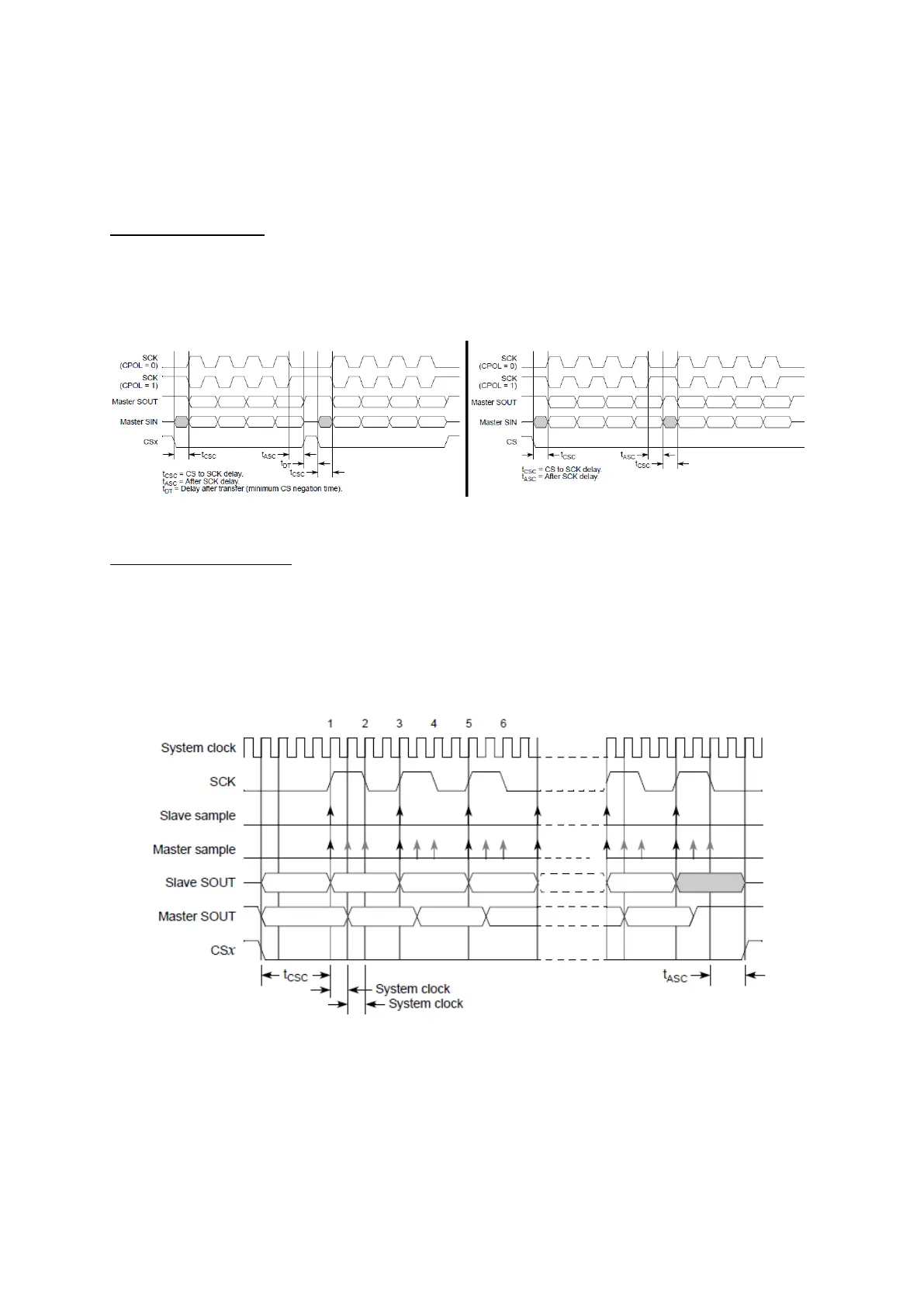
SMPL_PT: Sample point, allows the moment where the master can sample the SIN pin
when using modified transfer format: at the odd-numbered-edge of SCK(00), one system
clock cycle following that(01) or two system clock cycles following the SCK edge(10).
HALT: When set, DSPI transfers are stopped. Useful for starting/stopping transfers.
Some chips need to be deselected between two sequential transfers, others need to be keep
selected. By default, the delay after transfer (see below) allows the deselecting, but it can be
removed using continuous transfer mode.
Figure 90 : Difference between continuous and non-continuous formats (R.M. Rev8 –Fig. 23-20/21)
Modified transfer format:
On classical SPI transfer formats, CPOL and CPHA are enough to define the clock polarity and
which edges to use for capturing or changing the data. The modified transfer format allows to
refine the sampling point for applications where the slave chip might have a considerable delay
for changing its transmitted value. Using SMPL_PT the software can set a few system clock ticks
of delay for sampling. The user needs to check that SPI link timing won’t cause any problems.
Figure 91 : Modified transfer format (R.M. Rev8 –Fig. 23-18)
2.3.
Transfer Configuration Register
Each DSPI module contains six Clock and Transfer Attributes Registers[0…5](CTARx), that
define different settings for SPI’s transfer format like the frame size, baud rate, delays etc. When
transmitting, the software can select which CTAR register to use to set the transfer. These