Following configurations are needed in the SIUL module.
Output pads(Tx) need an output buffer, so the OBE bit SIUL’s pad configuration register is
needed. Also the slew rate of the port might need improving so SRC bit should be set.
For the input types the input buffer has to be enabled using IBE and also a pull up resistor is
needed, so the internal pull up can be used by setting WPE and WPS.
LINFlex Module Configuration
For power and clock cycle saving issues, the LINFlex module comes with a finite state machine
for controlling its status.
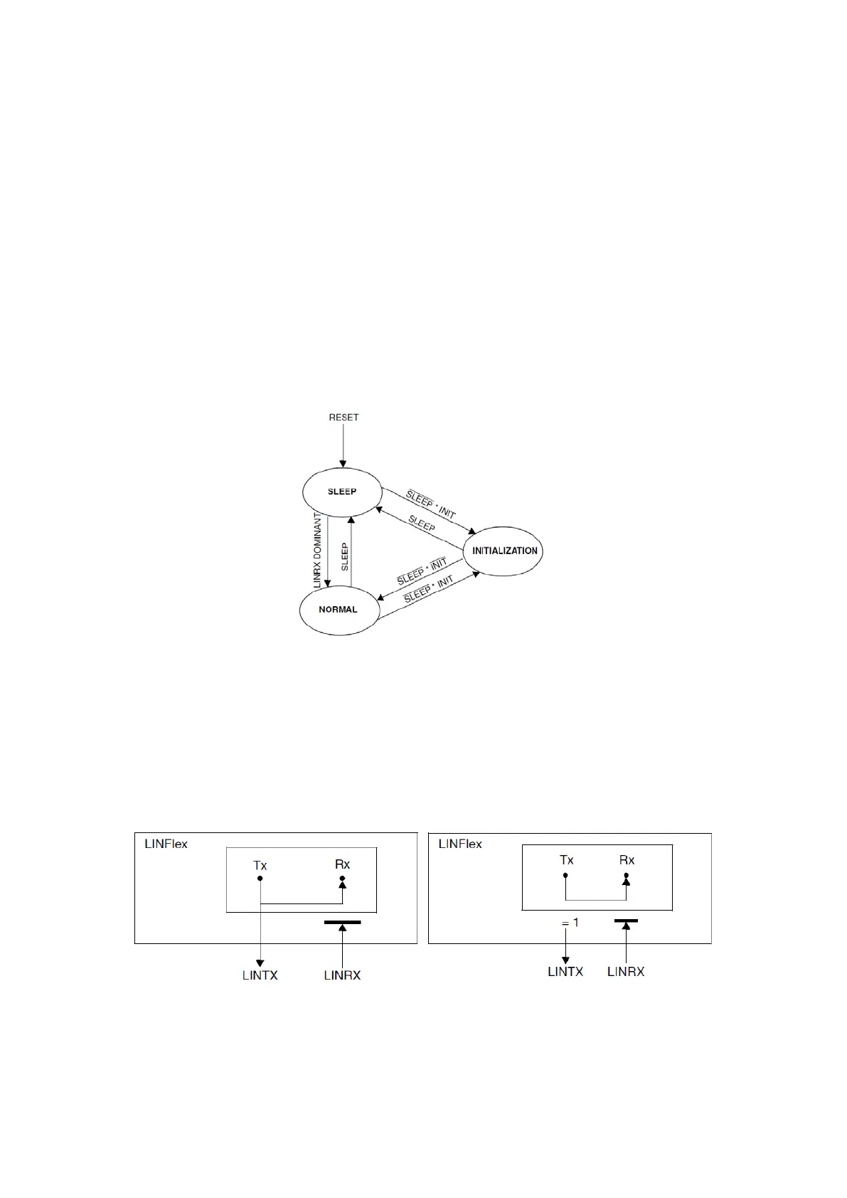
Figure 98 : LINFlex operating modes (R.M. Rev8 –Fig. 21-3)
There are three operating modes as shown on the figure above, the sleep mode is the low power
state, normal mode is the state where a communication is possible and the initialization mode is
a safe state where this module’s registers can be configured. Most of the transitions is done using
SLEEP and INIT bits of the LINFlex control register 1 (LINCR1), but it is possible to enable auto-
wake-up functionality which allows the module to switch automatically to normal mode
whenever a transmission or reception is needed.
Figure 99 : LINFlex in loopback and self-test modes (R.M. Rev8 –Fig. 21-4/5)
There are also two testing modes: Loop Back and Self-Test. In both of this modes, Tx of the
module is connected to the Rx, but in the Loop Back mode Tx is also connected to the external
devices whereas in Self-Test it is not possible.