any problem, but if it’s above then we’ll have to wait the counter to roll-over for getting normal
operation.
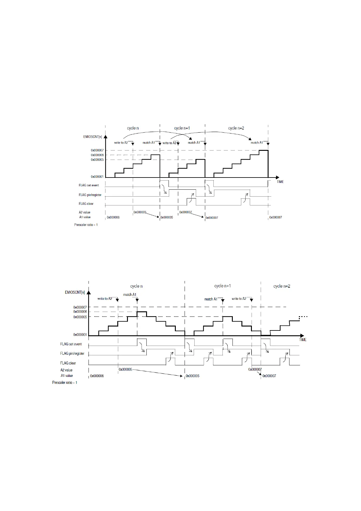
MCB: Modulus Counter Buffered
In this Modulus Counter Buffered mode (MODE[0:6]=1010b0b), the register A is double
buffered, allowing smoother transitions when the value of A is changed. The match register A1 is
only updated at the end of a cycle, avoiding the need of wait for a roll over. Another main
difference with the MC mode is that the counter counts between 0x1 and A1 value.
Figure 55 : MCB Up Counter Mode Example (R.M. Rev8 – Fig. 24-32)
The configurable bits MODE[4] and MODE[6] have the exact same effect as on the MC mode.
When the counter is in up mode, the period will take A1 cycles and when it is in up/down mode
it will take 2(A1-1) cycles.
Figure 56 : MCB Up/Down Counter Mode Example (R.M. Rev8 – Fig. 24-33)
MCB should be preferred over MC for clock generation.
OPWFMB: Output Pulse Width and Frequency Modulation Buffered
The Output Pulse Width and Frequency Modulation Buffered mode (MODE[0:6]=10110b0) is
used to generated waves with variable duty cycle and frequency. This mode automatically uses
the internal channel counter as it’s time base and comparators on A1 and B1.