48
ADC: Analog-to-Digital Converter
1.
Presentation of the ADC module
1.1.
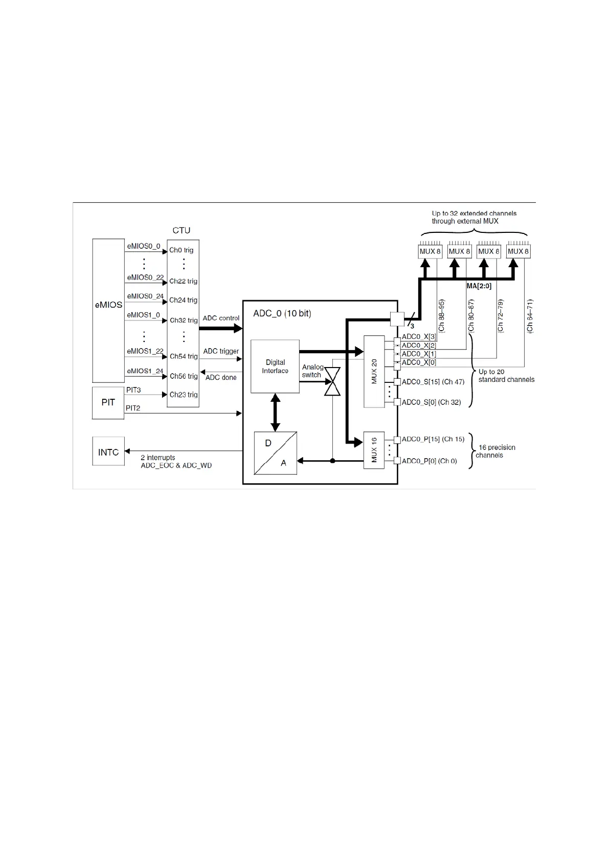
Figure 64 : ADC Architecture (R.M. Rev8 – Fig. 25-1)
The ADC block is made of multiplexing of 32 channels (expandable to 64 via external
multiplexing) to a 10-bit resolution, successive approximation converter.
A conversion can be triggered by software or hardware (PIT or CTU) and there are different
conversion modes like one shot or scan. There is also a chain injection possibility. Each channel
has individual conversion registers.
There are three types of input channels; 16 internal precision ADC0_P channels, 16+4 internal
standard ADC0_S channels, externally multiplexed standard channels ADC0_X. MA[2:0] pins are
for decoding external multiplexers.
Different timing configurations can be set for these different channel types.
There are 4 analog watchdogs monitoring lower and higher thresholds with interrupt
capabilities.
Pre-sampling functionality exists for higher quality data.