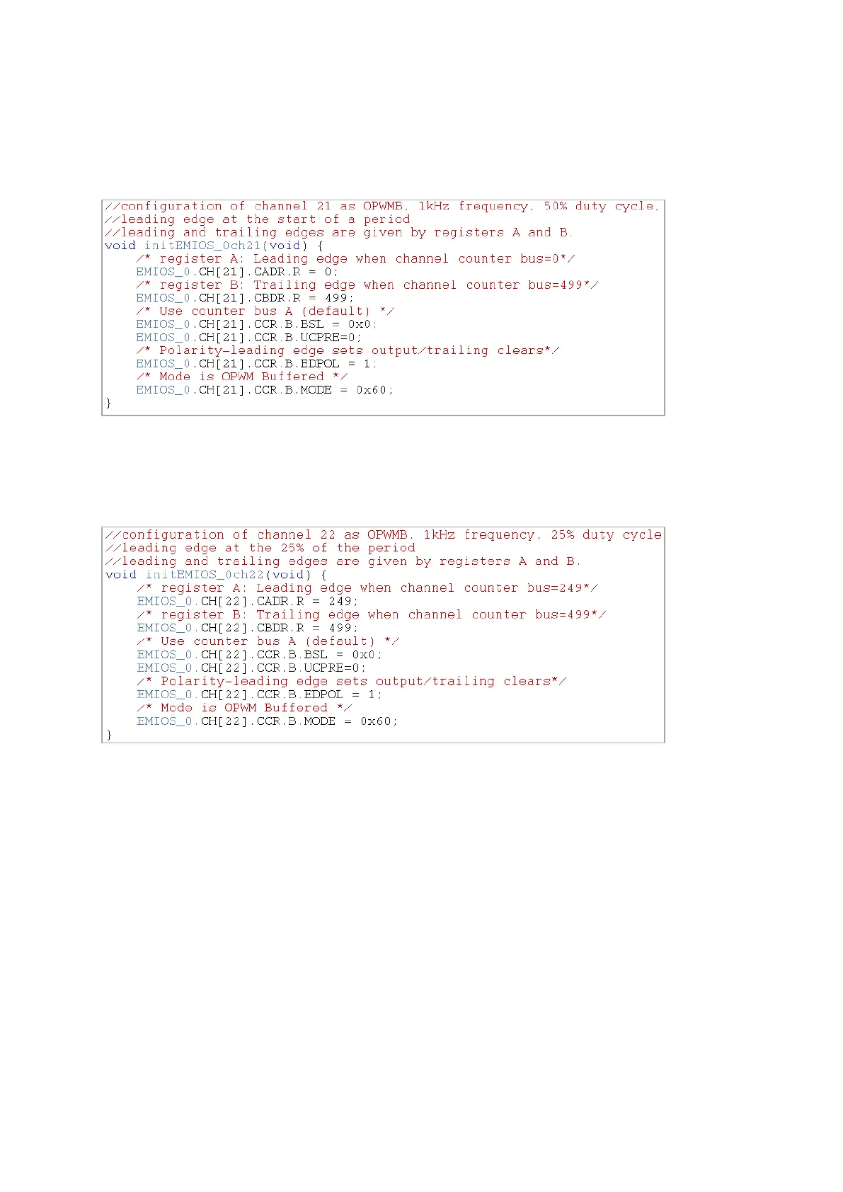
Now we have counter bus running, we can select any channel connected to the bus A and
configure it as OPMWB. For instance we can select channel 21, set the leading edge (register A)
at 0 and trailing edge at 499, running on bus A, with a positive polarity (output is set at leading
edge etc.).
This gives us a PWM at 1kHz with 50% duty cycle.
Similarly we configure channel 22 for a PWM at 1kHz with 25% duty cycle, with a leading edge
at 25% into a period.