Each of the four clock source has a single control register for its gating towards next blocks. We
will focus only on FXOSC’s control register.
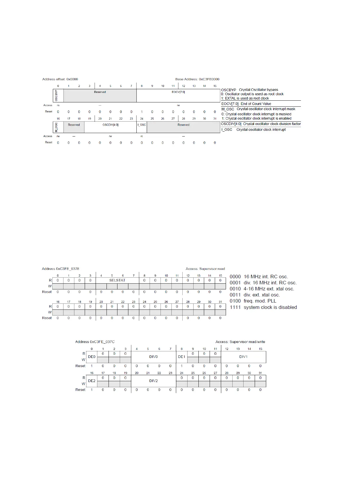
Figure 13 : Fast External Crystal Oscillator Control Register (Reference Manual Rev8 – Fig. 6-2)
Bypass allows using original crystal signal as clock without going through the oscillator, end of
Count Value is used to check the stability of the clock once the software powers it up. Once a
counter reaches the value EOCV [7:0]×512, if M_OSC is set and interrupt is generated, which has
to be cleared by setting I_OSC to 1, and the clock is ready to be used. The clock is divided by
DIVCLOK+1.
Other clock sources control register are similar with some different features: RC oscillators can
be trimmed by the software to increase precision (FIRC can be up to ± 1% precise) and the
SXOSC has a stability checking field (see chapter 6.3 to 6.6 in reference manual Rev8).
And finally, there are two registers for system clock management, one for reading the selected
source (by ME) and the other one is for managing peripheral clock gating.
Figure 14 : System Clock Select Status Register (Reference Manual Rev8 – Fig. 7-4)
Figure 15 : System Clock Divider Configuration Registers (Reference Manual Rev8 – Fig. 7-5)
DE fields of this register are to enable a divider and the value of division is DIV+1(up to 16).