It can be seen that there are two registers that are used for configuring pads; PCR (Pad
Configuration Register) and PSMI (Pas Selection for Multiplexed Inputs).
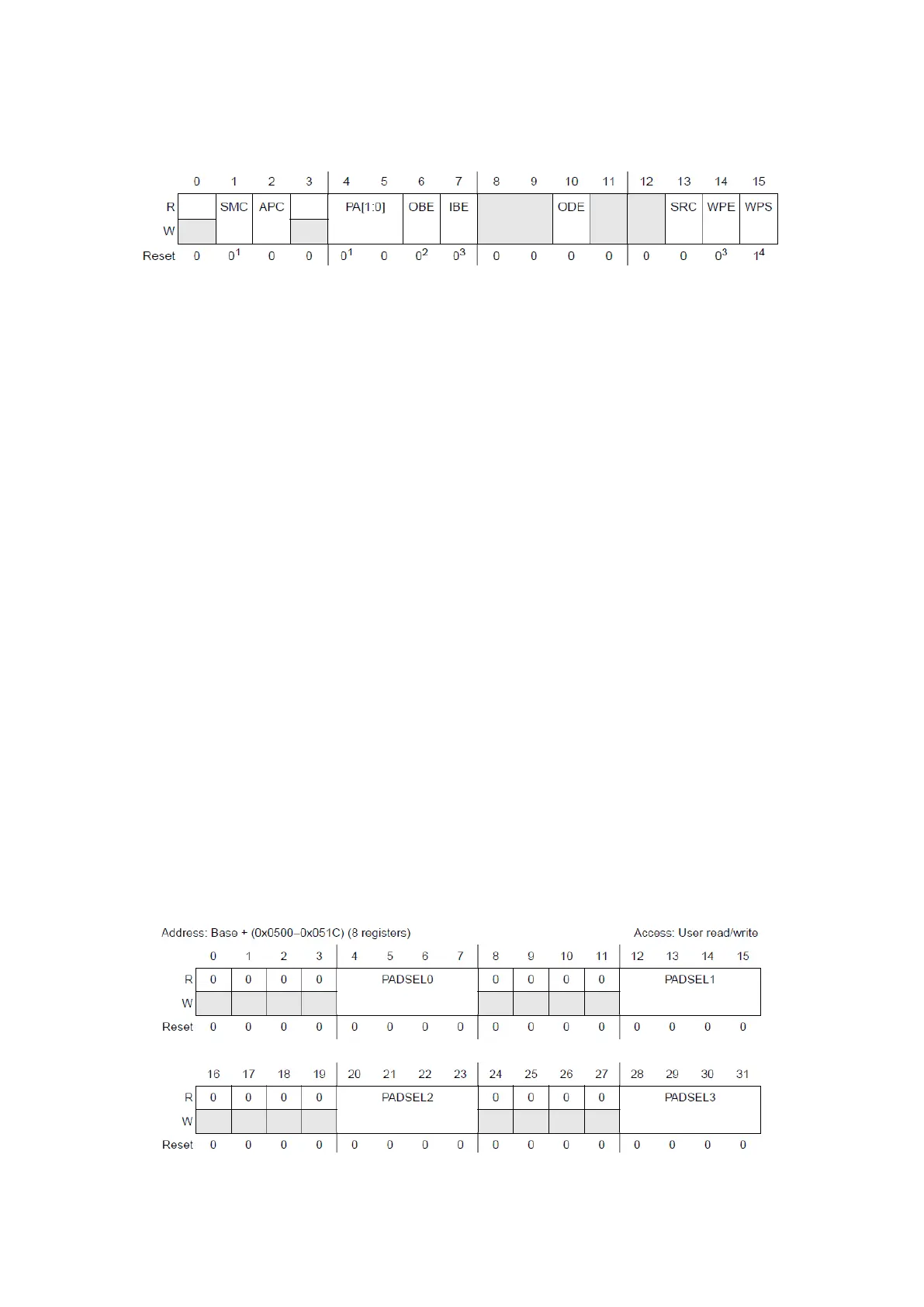
Figure 22 : Pad Configuration Register (Reference Manual Rev8 – Fig. 19-9)
There are 123 PCR registers, one for each pad, with following fields:
SMC: Safe Mode Control, by default output buffers are disabled in SAFE mode; writing ‘1’
to this bit keeps outputs functional.
APC: Analog Pad Control, this bit allows the use of the analog input path from the pad by
the ADC.
PA[1:0]: Pad Assignment, each pad can have up to four output alternate functions,
function 00 being always the GPIO, this fields makes the selection. See Appendix 2
OBE: Output Buffer Enable, if the pad is configured as GPIO, this bit allows its use as an
output.
IBE: Input Buffer Enable, enables the input buffer of the pad.
ODE: Open Drain Output Enable, when this bit is ‘0’, pad is configured for push/pull
output and when it is ‘1’, pad is an open drain output.
SRC: Slew Rate Control, by default (‘0’) the pad is slow and writing ‘1’ makes it
configured as medium or fast depending on the pad.
WPE: Weak Pull Up/Down enabling bit. WPS: Selecting Pull Up (‘1’) or Pull Down (‘0’).
But some of these fields are not available for all pads. Pads of type S, M and F are GPIO pads with
digital alternate functions and cannot use APC field. J-type pads are digital pads with analog
functionality and all fields are available for them. And finally, I-type pads can only be used for
ADCs and their only available fields are APC and IBE.
Note: Push/pull outputs are faster and easier to use so for most applications, Open Drain output
should be used if multiple outputs are to be pulled up/down together to implement logic
operations. Open drains are mostly needed in some communication protocols like I²C or CAN.
The other register is shown on the figure below.
Figure 23 : Pad Selection for Multiplexed Inputs Register (Reference Manual Rev7 – Fig. 8-10)