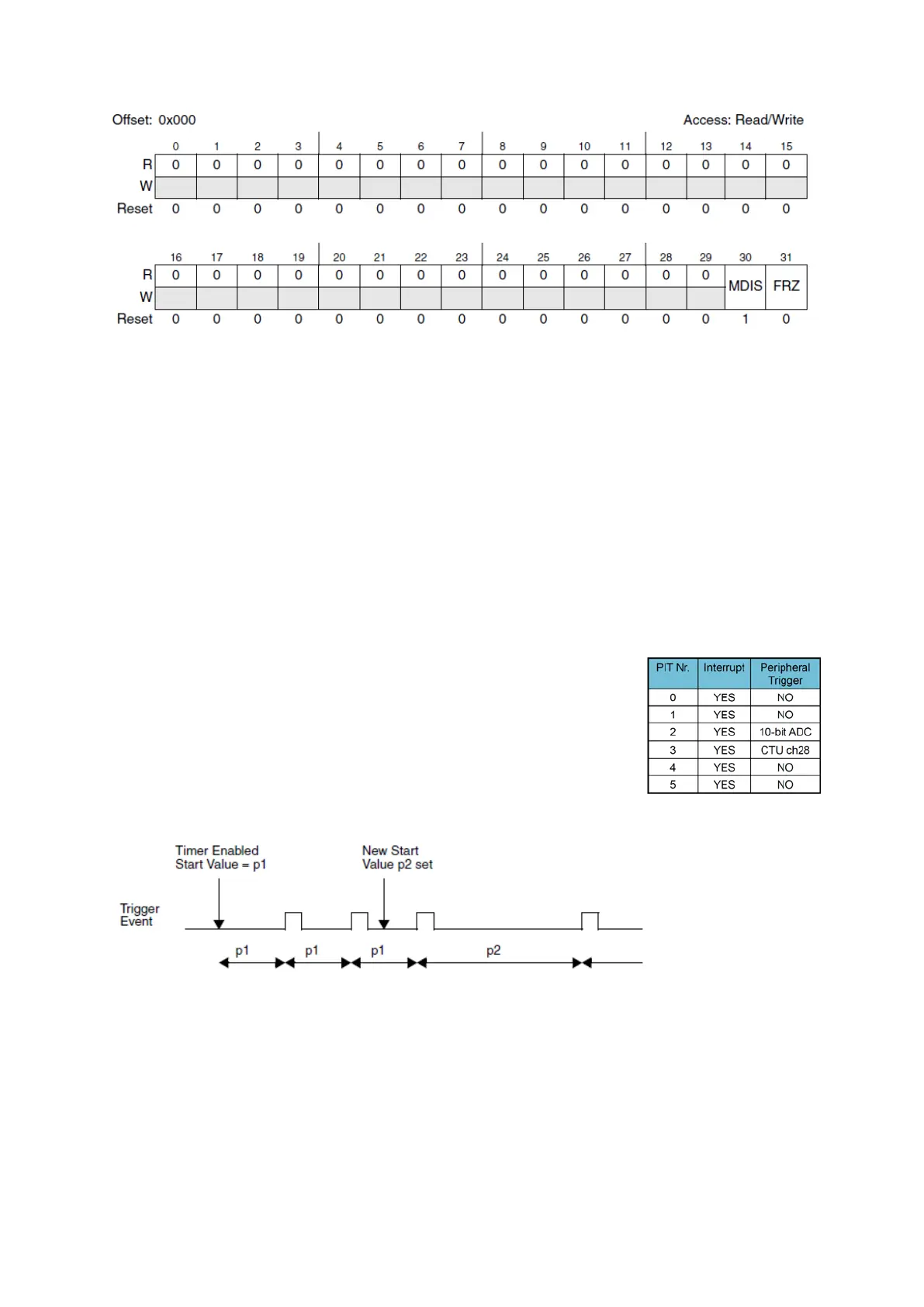
Figure 37 : PIT Module Control Register (R.M. Rev8 – Fig. 24-57)
The module is disabled by default, to enable it; we have to write ‘0’ to MDIS (Module Disable)
field. The FRZ field allows stopping the timers in debug mode by writing ‘1’.
Each of the six timers [0...5] have the following registers:
Timer Control Register (TCTRL) with a 1-bit timer enable (TEN) field and another 1-bit
timer interrupt enable (TIE) field.
Timer Load Value Register (LDVAL) with a 32-bit TSV (Timer Start Value) field.
Current Timer Value Register (CVAL) with a 32-bit TVL (Timer Value) field.
Timer Flag Register (TFLG) with a one bit timer interrupt flag field TIF (write ’1’ to clear
the flag).
Disabling then enabling a timer will restart à new period for the timer
(LDVAL loaded in CVAL). The timer automatically loads LDVAL in CVAL
when it reaches 0 and triggers an interrupt. It is possible to change
LDVAL value while the timer is running; the timer will load the new
value on the next trigger event.
Figure 39 : Changing Timer Period (R.M. Rev8 – Fig. 24-64)
Figure 38 : Some PITs can
trigger a peripheral event