Fields of this register are defined as; IDF[3:0]=IDF-1; and IDF [3:0] =1111 means clock
inhibition, ODF[1:0]=log
2
(ODF)-1, NDIV[6:0]=NDIV. These values must only be changed while
the PLL is not the system clock source. The other fields on this register are defined as:
EN_PLL_SW: Progressive clock switching, improves the PLL’s transition but the clock will
only reach PHI after a few cycles (192/PHI secondsng 64MHz).
UNLOCK_ONCE is set once the FMPLL loses lock. It will only be cleared on system reset.
I_LOCK is set each time a lock or unlock event occurs. It’s cleared by writing ‘1’.
S_LOCK: lock(‘1’)/unlock(‘0’) status of FMPLL.
PLL_FAIL_MASK: used to mask the pll_fail output (write ‘1’ to mask).
PLL_FAIL_FLAG: is set to ‘1’ once a loss of lock occurs while PLL is on. Cleared by writing
‘1’.
Here’s an example of using an 8 MHz crystal oscillator to generate a 45MHz system clock. Having
NDIV=90, IDF=2, ODF=8 allows us to get this output frequency while VCO frequency remains at
8x45=360MHz. All values are within constraints.
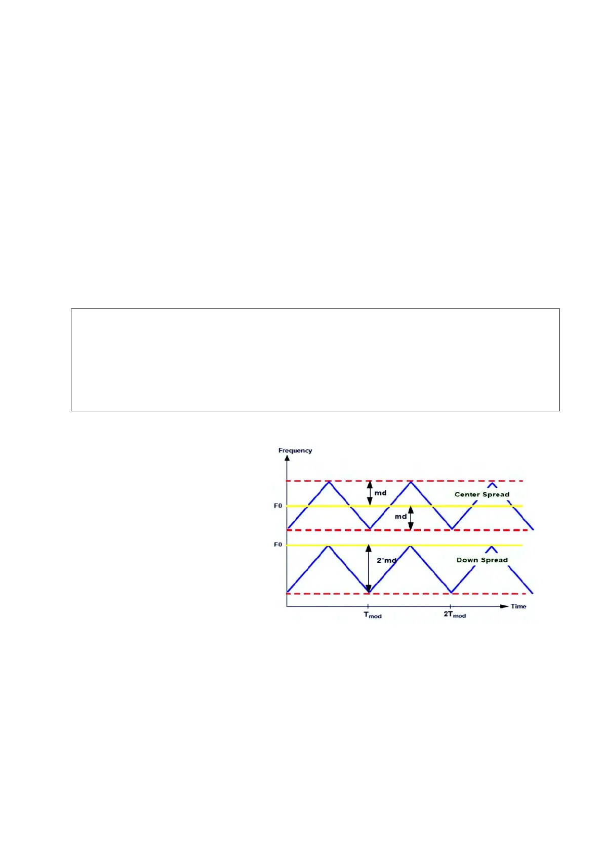
At this point, we only looked at the PLL aspect of the FMPLL module; this module can also
modulate the clock using frequency modulation with a triangular wave. This will help reduce the
effects of electromagnetic interference
generated by the high frequency
harmonics caused around the VCO
(from hundreds of MHz to up to a few
GHz) in the PLL. The electromagnetic
radiations on a specific frequency can
interfere with a surrounding
communication bands and cause errors.
By modulating the clock, its spectrum
will get wider and the energy at a
specific frequency will be less
important. Meanwhile the modulation
depth’s size can be critical in some
applications (like CAN) where FM can
cause errors. FM can be configured
using modulation register.
Frequency modulation can be configured with specifications on (modulation depth)
and
, modulation frequency. Modulation frequency should not be higher than 100kHz and
depth should not be higher than ±4%.
Figure 18 : FMPLL with its different spread modes (Reference
Manual Rev8 – Fig. 6-10)
CGM.FMPLL_CR.B.IDF = 1; //IDF[3:0]=IDF-1=2-1=1
CGM.FMPLL_CR.B.ODF = 2; //ODF[1:0]=log2(8)-1=3-1=2
CGM.FMPLL_CR.B.NDIV = 0x5A; //0x5A=90
CGM.FMPLL_CR.B.EN_PLL_SW = 1; //progressive transition
//these 4 lines are equivalent to CGM.FMPLL_CR.R = 0x065A0100
/* Here insert code that configures a user mode’s system clock with FMPLL,
you can check it with CGM.SC_SS.R read only register */