18
Installing and connecting inverter
Safety
Inverter Con-
struction
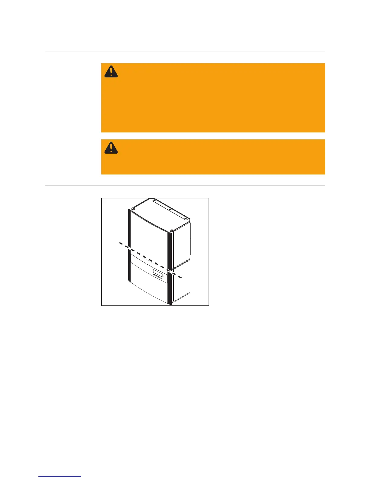
The power stage set and the connection
area are separated from each other for de-
livery.
(1) Power stage set(s)
(2) Connection area
WARNING! An electric shock can be fatal. Danger from grid voltage and DC volt-
age from solar modules.
- The connection area should only be opened by a licensed electrician.
- The separate power stage set area should only be disconnected from the
connection area after first being disconnected from the grid power.
- The separate power stage set area should only be opened by Fronius-trained
service personnel.
Never work with live wires! Prior to all connection work, make sure that the AC
and DC wires are not charged.
WARNING! If the equipment is used or tasks are carried out incorrectly, serious
injury or damage may result. Only qualified personnel are authorized to install
your inverter and only within the scope of the respective technical regulations. It
is essential that you read the "Safety regulations" chapter before commissioning
the equipment or carrying out maintenance work.
(1)
(2)

 Loading...


